Code Blue
• 259 Hedcor Street • Holland, MI 49423 USA • 800.205.7186 • www.codeblue.com
page 34 of 43 GU-149-Z1
CB 2 Series
Administrator Guide
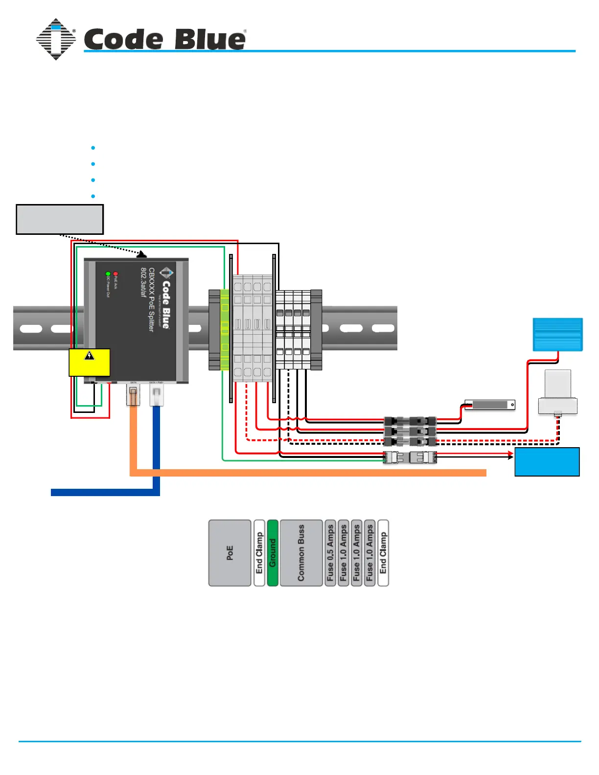
CB 2-a & CB 2-e PoE Standard DIN Rail Wiring
1 2 3
3 2 1
2 12 12 1
1 21 21 2
Faceplate Light
(CB 2-a Only)
Area Light
(CB 1-s Only)
Beacon Strobe
Incoming PoE >>>
Data to WAN Port of VoIP Speakerphone >>>
For installations with PoE incoming power on site.
Used in the following configurations:
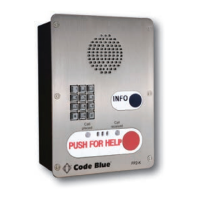
Standard CB 2-a - No Cellular Communication
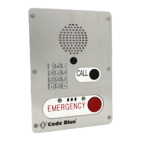
Standard CB 2-e - No Cellular Communication
Standard CB 2-a with Cellular Communication
Standard CB 2-e with Cellular Communication
DIN Rail Layout
Order of Connection
Connect Lighting & Communication devices to power system via Wago plug & socket
connectors.
1.
Connect RJ45 ethernet cable (Cat5e or Cat6) from “Data” port on PoE splitter to the
WAN port of the VoIP speakerphone.
2.
Plug incoming PoE ethernet RJ45 cable (Cat5e or Cat6) into “Data + PoE” port on PoE
splitter. Splitter will light up accordingly indicating passing of DC voltage.
3.
IMPORTANT NOTE: LS1000 speakerphones operate on 12V DC only. If the 24V DC output is selected on the
PoE splitter, the use of a 24V to 12V DC step-down transformer must be installed prior to connecting the
power system to the speakerphone.