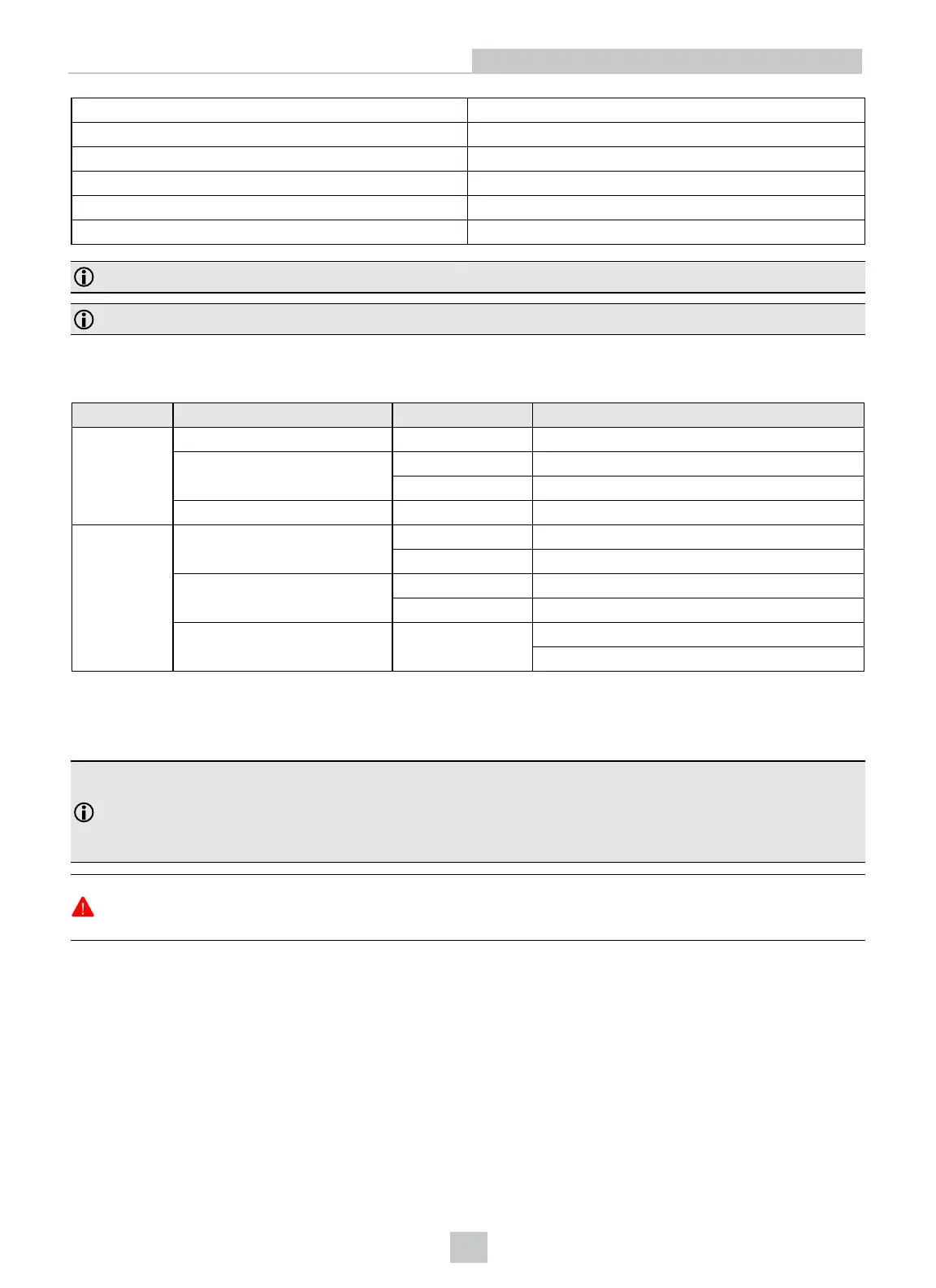
8
Good/bad read indicator
9
Network status indicator
10 Error indicator
11 Tune button
12 Power, I/O and RS-232 connector
13 Ethernet connector
Note: *Use only one set of mounting holes (either 3 OR 4) for mounting.
Note: The five status LEDs together also function as a peak meter using an orange light.
Indicator LEDs
Type Signal Color Meaning
Status Power GREEN Power ON
Train status GREEN Trained
YELLOW Untrained
Error RED Error - check device log
Action
Good/bad read
GREEN Good read
RED Bad read
Network YELLOW Link up
blink
Data transfer
Peak meter Yellow Tune
Focus
Changing Orientation
Perform the following steps to change between in-line and right-angle configuration.
Note:
l Switching between in-line and right-angle configuration is recommended only up to 10 times in the lifetime
of the DataMan 260.
l Disconnect the DataMan 260 from power before changing the orientation.
WARNING: Make sure that no electrostatic charges are applied to the PCB. (e.g. wear ESD shoes.) If the main
module is separated from the I/O connector module, take care to assemble them correctly. Otherwise, the IP rating
can be compromised.
13
Getting Started



 To Next Page