Collamat S Series
Inputs + Outputs
56 Release: V1.15/05/2013
Explanation
The figure above shows a diagram of the rapid optical coupler
inputs with separate anode and cathode cables.
With this type of input, PNP, NPN as well as push-pull output
signals can be connected. The input is active if a current of
approx. 4 mA (at 24V) flows through the LED of the optical
coupler. The maximum input voltage is 28V.
The following input signals fall under this category:
Rapid optical coupler inputs
Input Description
TACA_P
Incremental encoder (tacho) - phase signal A
TACB_P
Incremental encoder (tacho) - phase signal B
4.1.2 Label sensor – inputs
Explanation The only analog inputs in the Collamat S are the two inputs of the
label sensor.
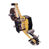
The standard label sensor consists of an OP550A phototransistor
receiver that is built into the housing of the sliding label sensor
head. The active signal passes through a shielded cable to the
adapter electronics in the adapter housing.
Here, the signal is converted and sent to the main control unit (in
the Collamat S housing) over the adapter ribbon cable. A rapid
operation amplifier switch sends the analog active signal to the
slave controller.
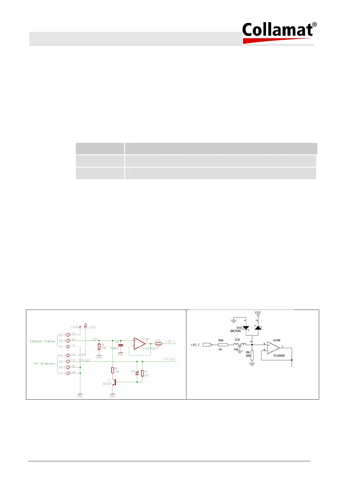
Figure below shows a basic diagram for the analog inputs:
Basic diagram – Analog sensor(s) - Sensor 1 and optional Sensor 2 (analog sensor 2 – only for HMS-units)