14. Turn off the appliance, turning the main machine switch (1) to "0",
and turn the key (2) a quarter turn to the left ( Fig.1). Remove the
key from the instrument panel.
15. Grip the handle (3) on the left side of the recovery tank (Fig.2) and
turn the tank as far as it will go, until it reaches the maintenance
position (Fig.3).
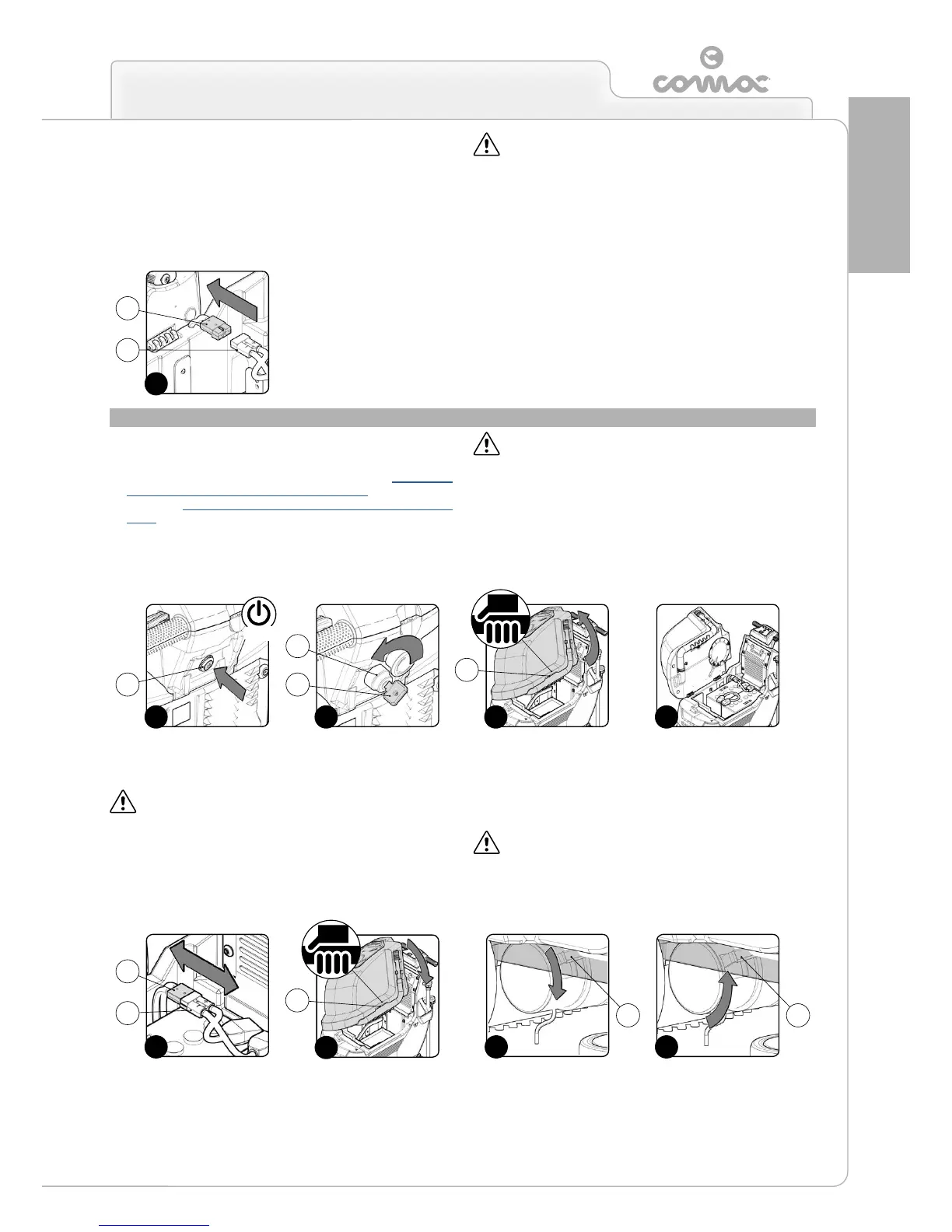
16. Disconnect the battery hopper connector (4) from the connector
of the general system (5) Fig.13).
ATTENTION: This process must be carried out by qualied
personnel.
17. Grip the handle (3) on the left side of the recovery tank and turn
the tank until it reaches the work position (Fig.5).
HOW TO TRANSPORT THE APPLIANCE
To transport the machine, proceed as follows:
1. Check that the solution tank and recovery tank are empty. If
they are not, empty them (read the paragraph “CHECKING
AND CLEANING THE RECOVERY TANK” or read the
paragraph“CHECKING AND CLEANING THE SOLUTION
TANK”).
2. For B versions, make sure the device is switched off. If it isn't,
press the main switch (1) on the back of the device (Fig.1).
ATTENTION: in B versions, the main switch (1) is in the idle
position when the LED inside it is OFF and the activation
symbol is not visible.
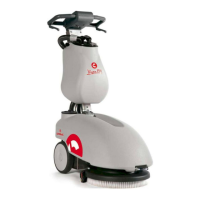
3. For BT versions, make sure the device is switched off. If it isn't,
bring the main switch (2) to the “0” position by making a quarter
turn to the left with the key (3) (Fig.2). Remove the key from the
instrument panel.
4. Grip the handle (4) on the left side of the recovery tank (Fig.3) and
turn the tank as far as it will go, until it reaches the maintenance
position (Fig.4).
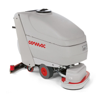
5. Disconnect the connector of the general system (5) from the
connector of the batteries (6)Fig.5).
ATTENTION: This process must be carried out by qualied
personnel.
6. Grip the handle on the left side of the recovery tank and turn the
tank until it reaches the work position (Fig.6).
7. For BT versions, release the electronic brake and turn the lever
(7) in the direction of the arrow. The traction gearmotor is located
on the left side of the device (Fig.7).
8. Using a chute, slide the machine onto the pallet.
9. For BT versions, engage the electronic brake and turn the lever
(7) in the direction of the arrow. The traction gearmotor is located
on the left side of the device (Fig.8).
10. Secure the device to the pallet using the wedges.
ATTENTION: for transportation without a pallet, secure the
device according to the directives in force in the country of use
so that it does not slide or tip over.
5
4
13
3
3
7
1 3
2
6
5
4
4
1 2
5
OFF
4
8
7 7