Inteli NT GeCon MINT, SW Version 1.4, ©ComAp – June 2007
IGS-NT-GeCon-MINT-1.4.PDF
60
Hint:
When set to NEGATIVE, Binary outputs AVR Up and AVR Dn still work without inversion.
Voltage gain [ % ]
Gain of voltage control loop.
Step: 0,1 %
Range: 0,0 to +200,0 %
Voltage int [ % ]
Relative integration factor of voltage control loop. Increasing of integration value causes quicker response.
Step: 1 %
Range: 0 – 100 %
Hint
:
Voltage gain and Voltage int setpoints are active (adjust AVR) when GCB is open to maintain the Nominal
voltage or to match voltage during synchronizing. Voltage loop operates as well in single island operation.
PF gain [ % ]
Gain of power factor control loop.
Step: 0,1 %
Range: 0,0 – 200,0 %
PF int [ % ]
Relative integration factor of power factor control loop. Increasing of integration value causes quicker
response.
Step: 1 %
Range: 0 – 100 %
Hint:
When any gain setpoint is set to zero, the corresponding control loop is switched OFF.
PF gain and PF int setpoints are active only when the gen-set runs parallel to mains.
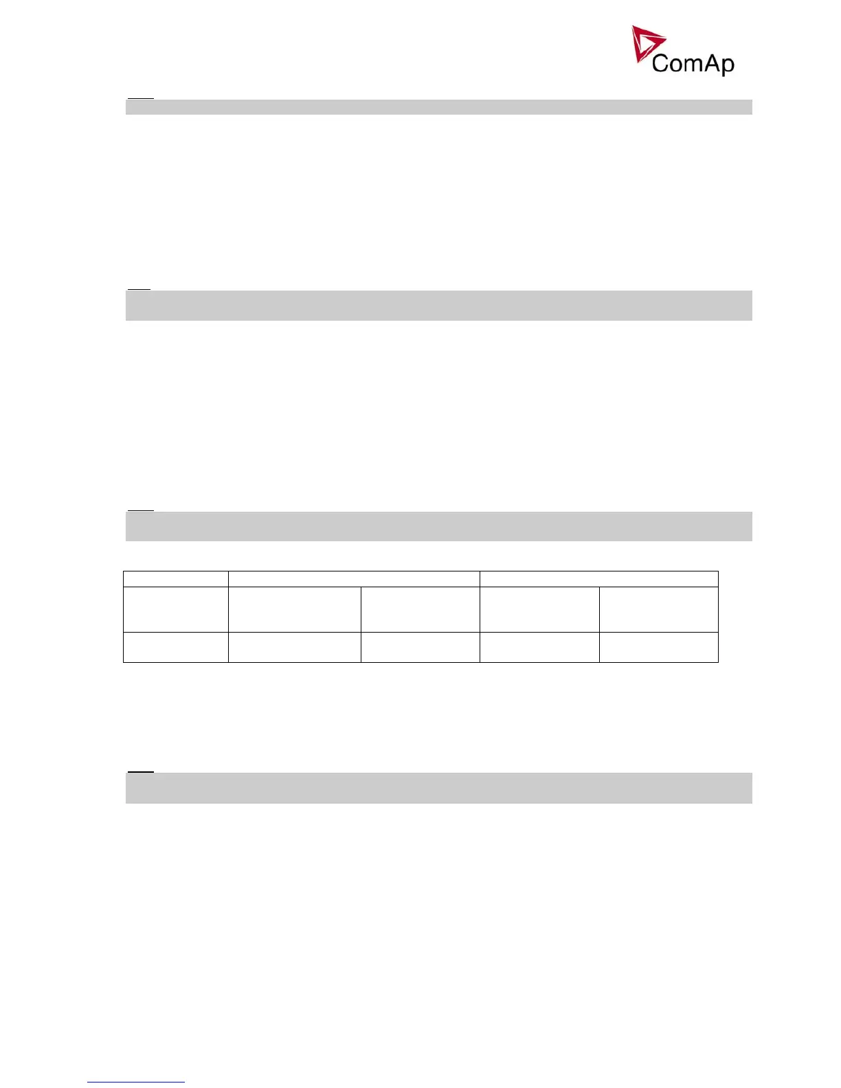
VoltRegOut behavior in single-gen-set applications
Operation mode Island Parallel to mains
Gen-set state Running,
GCB opened
Loaded island
GCB closed
MCB opened
Synchronizing Loaded in parallel
GCB closed
Active loop:
Volt gain, int;
Active loop:
Volt gain, int;
Active loop:
Volt gain, int;
Active loop:
PF control
AVR DCout bias [ % ] (FV)
AVRi voltage output bias level. This is a basic voltage level of the output if there is no regulation loop active.
Step: 0,1 %
Range: 0 – 100,0 %
Force value: Yes
Hint:
Real voltage level depends on AVRi outputs connection and output level potentiometer setting. Maximum
range is ± 10 V.
VS gain [ % ]
Gain of VAr sharing control loop.
Step: 0,1 %
Range: 0,0 – 200,0 %
VS int [ % ]
Relative integration factor of VAr sharing control loop. Increasing of integration value causes quicker
response.
Step: 1 %
Range: 0 – 100 %