InteliLite
NT
– AMF20/25, SW version 2.2, ©ComAp – September 2014 34
IL-NT-AMF-2.2-Reference Guide.pdf
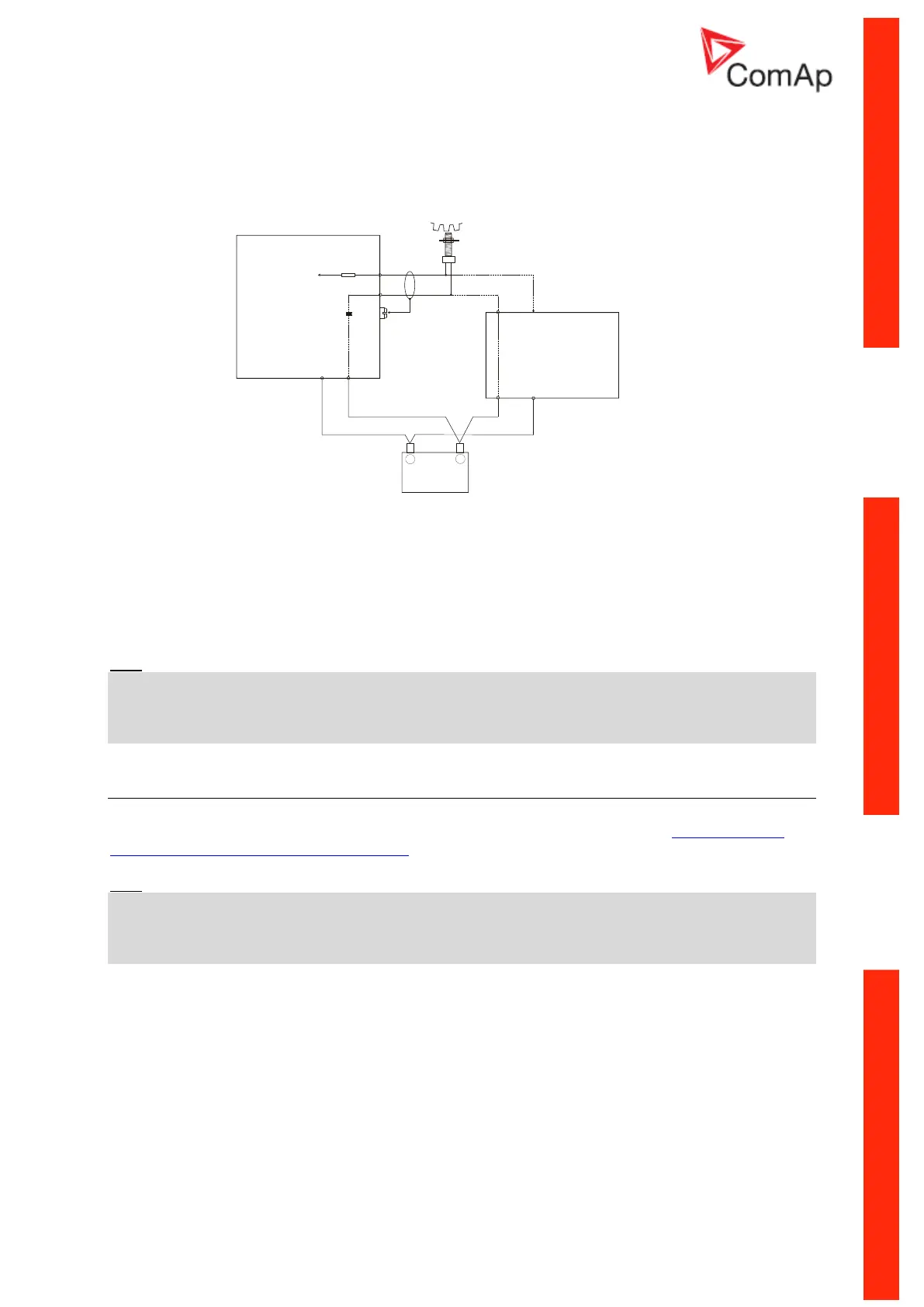
Magnetic pick-up
To ensure proper function:
Use a shielded cable
Be aware of interference signal from Speed governor when one speed pick-up is used.
If engine will not start:
- Check ground connection from pick-up to controllers, eventually disconnect ground connection
to one of them
- Galvanically separate InteliLite RPM input using ComAp separation transformer RPM-ISO
(1:1)
- Use separate pick-up for Speed governor and InteliLite
NT
Hint:
In some cases the controller will measure a RPM value even though the gen-set is not running:
RPM is measured from the generator voltage (Gear Teeth = 0)
IL-NT is measuring some voltage value on input terminals due to open fusing.
If RPM > 0 the controller will be put into a Not ready state and the engine will not be allowed to start.
Current measurement
The number of CT’s is automatically selected based on selected value of setpoint ConnectionType
[3Ph4Wire / 3Ph3Wire / Split Ph / Mono Ph].
Hint:
Further information about measurement limits are at setpoint CT Ratio [/5A] description in chapter
Setpoints - Basic Settings.
Generator currents and power measurement is suppressed if current level is bellow <1% of CT
range.
To ensure proper function:
Use cables of 2,5mm
2
Use transformers to 5A
Connect CT according to following drawings:
Three phase application:
+
Battery
-
iL
GAC
Speed Control Unit
ESD 5500
MAGNETIC
PICK-UP
C
D
a
b
Signal
Signal
+
+-
-
Power
Supply
Power
Supply