EasyManuals Logo

ComAp intelilite nt amf25 User Manual

ComAp intelilite nt amf25
145 pages
To Next Page IconTo Next Page
To Previous Page IconTo Previous Page
Page #41 background imageLoading...
Page #41 background image
InteliLite
NT
AMF20/25, SW version 2.2, ©ComAp September 2014 41
IL-NT-AMF-2.2-Reference Guide.pdf
Connection of IL-NT analog inputs
AI
1
AI2
3 x RESISTIVE
SENSOR
AI3
COM
- POWER
Standard connection of three resistive sensors
to analog inputs.
2
x
470
COM
-
POWER
AI1
AI2
AI3
Mixed connection of InteliLite analog inputs:
AI1 binary input
AI2 three state input
AI3 analog resistive input
Hint:
Description of analog inputs with COM terminal and 4 pins relates to units with HW version 1.3. Older
HW versions do not have “COM” terminal and use only 3 pins AI1, AI2 and AI3.
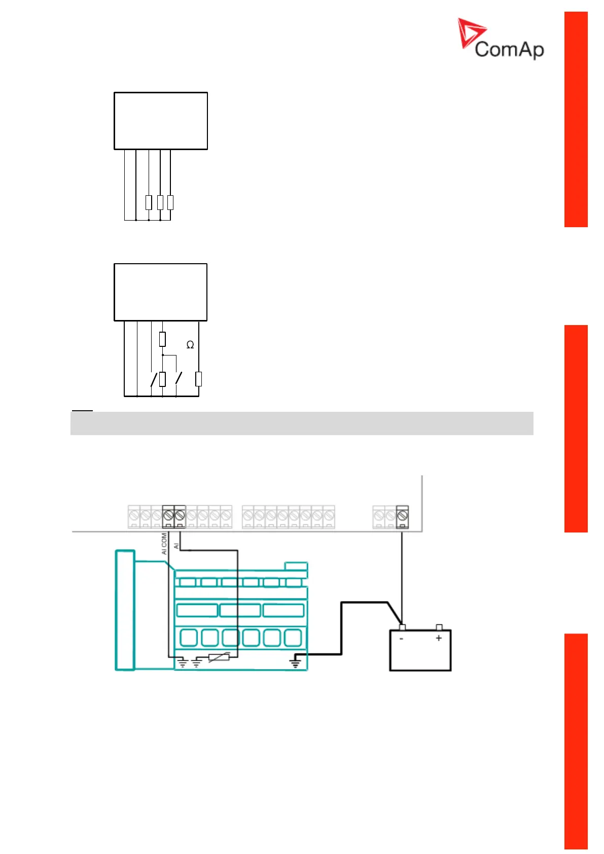
Wiring
Wiring diagrams of analog inputs since IL-NT HW 1.3:
WIRING OF ANALOG INPUTS-GROUNDED SENSORS

Table of Contents

Questions and Answers:

Question and Answer IconNeed help?

Do you have a question about the ComAp intelilite nt amf25 and is the answer not in the manual?

ComAp intelilite nt amf25 Specifications

General IconGeneral
Communication PortsRS232, RS485, USB
Power Supply8-36 VDC
Number of Digital Inputs8
Number of Digital Outputs8
Number of Analog Inputs3
Number of Analog Outputs2
DisplayLCD with backlight
Supported ProtocolsModbus
Operating Temperature-20°C to +70°C
Humidity95% non-condensing
Weight0.4 kg
ProtectionIP65 (front panel)
Controller TypeAMF Controller
Storage Temperature-30 to +80 °C

Related product manuals