Installation
Page 35
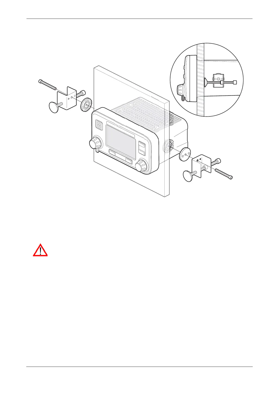
Figure 36 Panel mounting the AIS transceiver
4.3.2 Step 2 - Installing the junction box
The AIS transceiver receives data from the ship’s sensors via the 50 way data cable which connects to the rear
of the transceiver. The other end of this cable is connected to the junction box which provides a convenient
screw terminal system for connection of ships sensor data cables.
Please note the following guidelines when selecting a location for the AIS junction box:
● There should be adequate space around the junction box for routing of cables. See Figure 37 for
details of the junction box dimensions.
● The ambient temperature around the junction box should be maintained between -15°C and +55°
(5°F to 131°F).
● The junction box should not be located in a flammable or hazardous atmosphere such as in an engine
room or near to fuel tanks.
● The junction box must be installed in a 'below decks' environment protected from the weather.
● The transceiver is supplied with four self tapping screws for attachment of the junction box to a
suitable surface. Please refer to
Figure 38 for guidance.
● The junction box must be located within 1m (3.2ft) of the AIS transceiver to allow for the length of the
supplied data interface cable.
To meet IMO requirements the AIS transceiver must be able to transmit at least Speed over
Ground (SOG), Course over Ground (COG) and Rate of Turn (ROT) information. This data is
obtained by connecting data outputs from the ship’s DGPS, Gyrocompass and other sensors to
the transceiver via the junction box.