Installation
Page 39
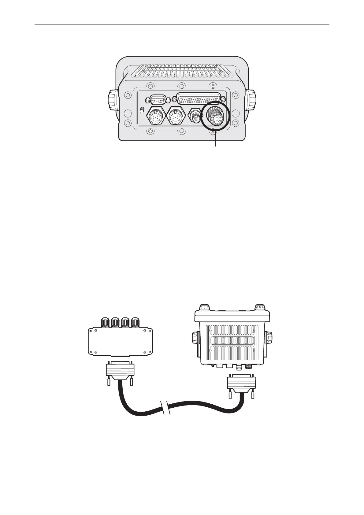
Figure 42 VHF antenna connection
4.4 Connecting the equipment
With the transceiver, junction box and antenna installed it is now possible to connect the equipment in
preparation for commissioning.
4.4.1 Antenna connections
If antenna connections have not already been made the GPS and VHF antennas should now be connected to
the transceiver. Refer to
Figure 40 and Figure 42 for guidance.
4.4.2 Data connections
The CSA-300 transceiver is supplied with a 1m (3.2ft) 50 way data cable for interconnection of the transceiver
and junction box.
Connect the junction box to the transceiver using the data cable as indicated in Figure 43.
Figure 43 Connecting the junction box to the transceiver