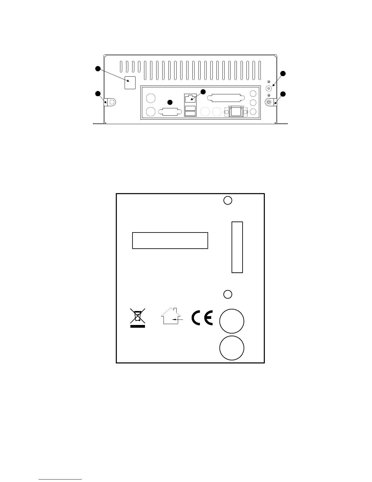
Figure 2 - Rear view of RF500 Gateway
A. Modem Jack – Connect to RJ11 line cord.
B. 12V DC input.
C. Cable clamps.
D. RJ45 Ethernet LAN Socket.
E. Rear panel connectors. Do not connect any equipment to any other connector.
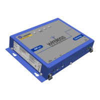
Figure 3 – Left Hand Side View of Gateway
SERIAL No
MADE IN UK
Comark Instruments Inc.
Comark Limited
www.comarkltd.com
Tel: 503 643 5204
Beaverton, OR 97005
Stevenage, Herts SG1 2TA
Tel: 01438 (+44 1438) 367367
RF500
GATEWAY
AUX
ON/OFF
SW1
SW2
STATUS
FOR INDOOR USE ONLY
DO NOT MOVE WHEN IN OPERATION
4
3
2
1
AUX Reserved Switch.
STATUS Reserved LEDs for Comark use.
ON/OFF Gateway Startup/Powerdown switch.
SW1 Jack Socket - Relay Output-1.
SW2 Jack Socket - Relay Output-2.
SW1 & SW2 are two switched outputs provided for connection to customer alarm indicators,
via relay contacts with 12V 500mA rating, configurable for either NO (Normally Open) or NC