(Normally Closed). These are marked as SW1 and SW2, and are in the form of 2.5mm Jack
Sockets. Suitable Jack Plugs are provided with each Gateway and if lost, spares are available
from Comark, part number RFJACK.
With the Gateway power removed the relays are in a Normally Closed condition, this
may cause any equipment connected to the contacts to energise.
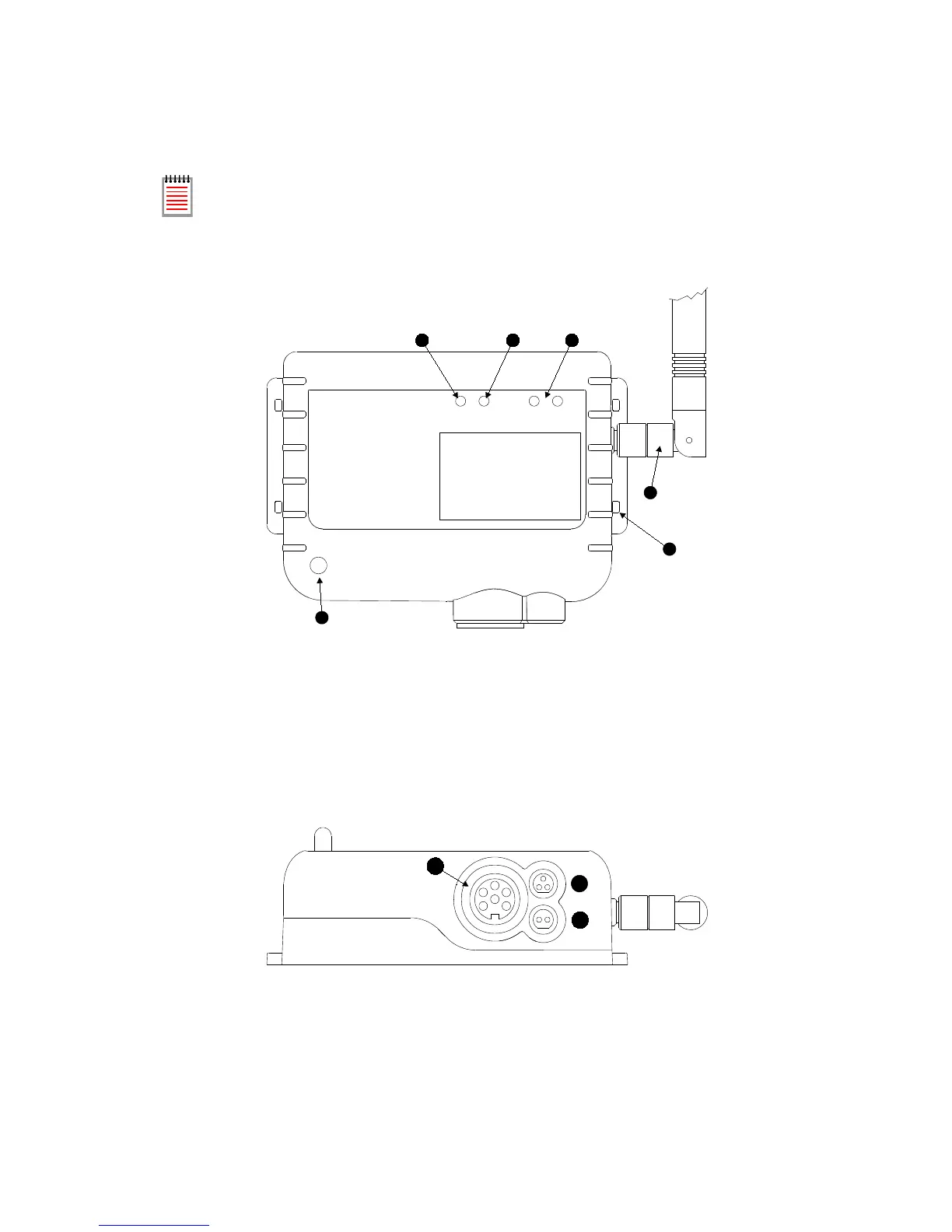
Know your Transmitter
Figure 4 - Front view of RF512 Series Transmitter
A. Alarm LED. Flashes red to indicate any one channel in alarm.
B. Active LED. Flashes green to indicate external power detected.
C. Infra-Red interface. For Comark use only.
D. Antenna. (Do not remove whilst in operation)
E. Lashing eye - Four available.
F. Internal temperature sensor.
Figure 5 - Connector view of RF512 & RF516 Transmitter
A. Lumberg Socket for Probe.
B. Socket for Door & RF525 Activator. (Dual function)
C. External DC adaptor socket.