Atena Easy Addressable Fire Alarm Panel – Installation and Programming Manual
10
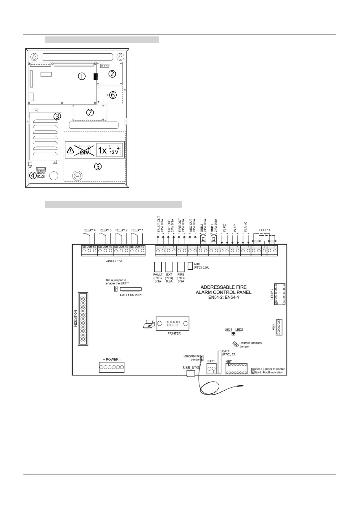
2.2.2 Configuration of the basic modules
Figure 6 – Configuration of the modules in the box:
1 – Main PCB (control panel)
2 – Second loop controller (optional, it may not be present in your
system configuration)
3 – Power supply unit
4 – Terminal 230V for connection of the main power supply cable
5 – Place for accumulator battery, 1 х 12V/ 18Ah
6 – Place for mounting of a communication module
7 – Place for mounting of redundant network module
2.2.3 Description of the main PCB (control panel)
Figure 7 – Main PCB of the Atena Easy fire alarm panel
Description of the terminal row (left to right):
RELAY 1 - 4 – Programmable volt free change over relay contacts each, 24VDC@15A. Each relay has one
NO (normal open) and one NC (normal closed) contact with common lead on a terminal. When a relay output
is activated the NO contact is closed and the NC contact is opened.
FAULT – Potential, monitored output for connection of auxiliary devices, 24 VDC/ 0.3А. This output is
deactivated in case of system trouble or fault.