Atena Easy Addressable Fire Alarm Panel – Installation and Programming Manual
43
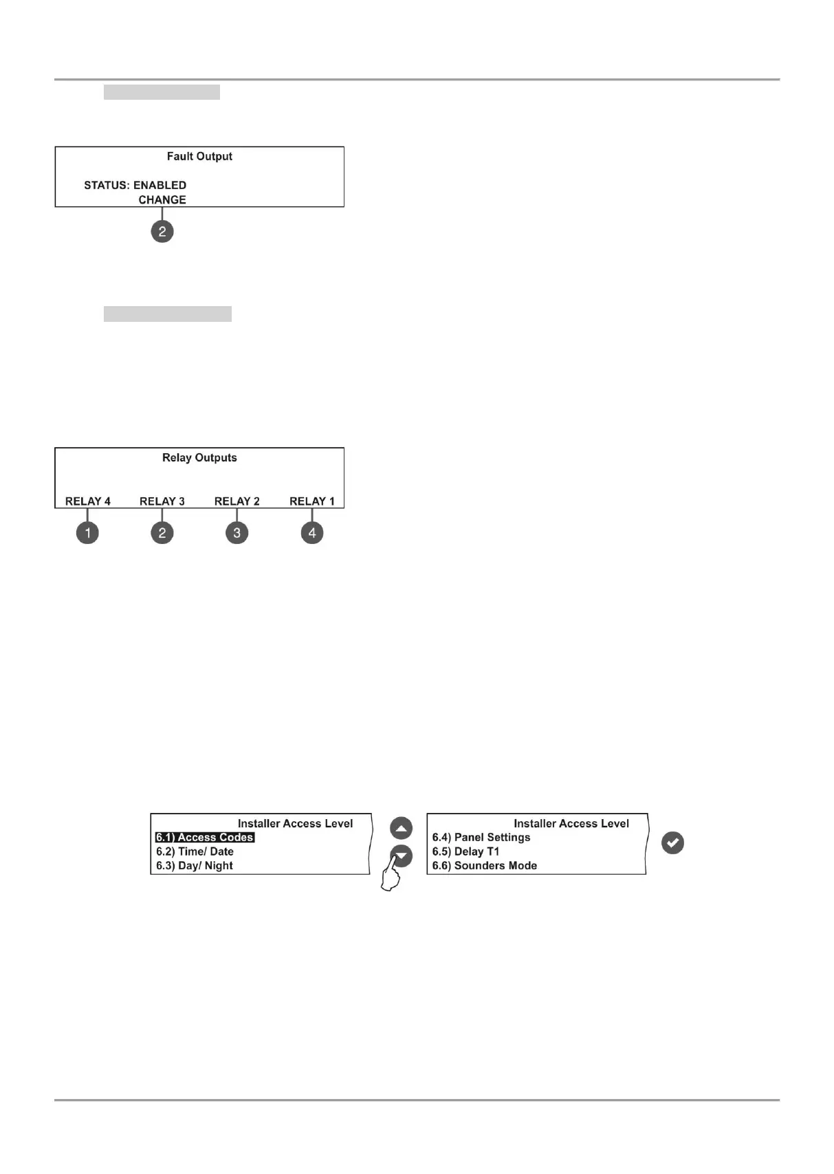
7.5.4 Fault Output
In this submenu the installer can disable/ enable the fault output activation.
To access the FAULT submenu, enter in the installer’s menu - 5. PANEL OUTPUTS – MORE> (4) – FAULT (1).
The functional button has the following action:
(2) - Press to change the status of the fault output. Every pressing of
the button changes alternatively the ENABLED - DISABLED status.
When the fault output is disabled the LED ‘Disable’ light on
permanently.
All set parameters are confirmed with ENTER button.
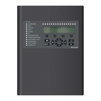
7.5.5 Relay Outputs
Attention: The relay outputs are available for setting parameters only from access level 3!
In this submenu the installer can the set parameters of the relay outputs on the control panel PCB.
To access the RELAY OUTS submenu, enter in the installer’s menu - 5. PANEL OUTPUTS - MORE>> - RELAYS (2).
Attention! The order of the relay numbers follows that on the control panel PCB!
The programming of the relay outputs is analogical.
Use the functional buttons to set parameters for:
1 - Press to set parameters for RELAY 4
2 - Press to set parameters for RELAY 3
3 - Press to set parameters for RELAY 2
4 - Press to set parameters for RELAY 1
For the settings of the relay outputs refer to the description of the menus for 41IOM004.
All set parameters are confirmed with ENTER button.
The exit to the main screen of PANEL OUTPUTS is with pressing the CANCEL button.
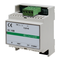
7.6. General Settings Menu
This menu allows the installer to make some common settings for the fire panel.
The menu is accessible from access levels 2 and 3, as for the level to are introduced some restrictions.
A list with submenus is displayed after entering the installer’s menu - 6. GENERAL SETTING. The currently selected
submenu is blinking. To enter into a submenu press ‘ENTER’.