1313
EN
Warning:
• Install the equipment by carefully following the instructions given by the manufacturer and in compliance with the standards in force.
• All the equipment must only be used for the purpose it was designed for. Comelit Group S.p.A. declines any responsibility for improper use of the apparatus, for modifi cations made by
third parties for any reason or purpose, and for the use of accessories and materials which are not originals.
• All the products comply with the requirements of Directive 2006/95/EC (which replaced Directive 73/23/EEC and subsequent amendments), as certifi ed by the CE mark they carry.
• Do not route the riser wires in proximity to power supply cables (230/400V).
• Installation, mounting and assistance procedures for electrical devices must only be performed by specialised electricians.
• Cut off the power supply before carrying out any maintenance work.
• Connect the module-holder frame to earth (see Fig.).
• Do not press and hold the audio hook while the handset is lifted.
• The camera must not be installed opposite bright light sources, or in places where the fi lmed subject is against the light. To resolve this problem, we
recommend modifying the installation height of the camera, which is usually 160 - 165 cm, to a height of 180 cm and pointing the lens downward so as
to improve fi lming quality.
• Cameras with colour CCD sensor have poorer sensitivity in low light conditions than black/white cameras. We therefore recommend, in dimly lit
environments, that an additional light source is installed.
General information
14
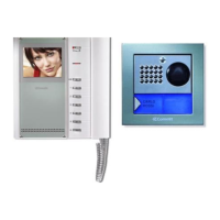
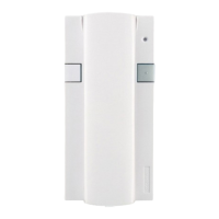
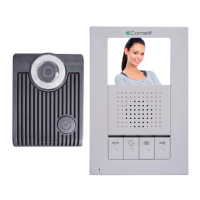
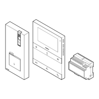
External unit
Art. 4879K 14
Art. 1207 14
Installing the external unit
14
Inserting nameplates
15
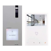
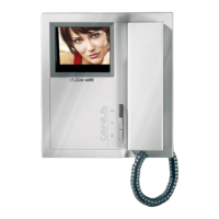
Internal units
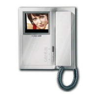
Art. 5701 16
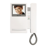
Art. 5714/K 16
Installing Art. 5701 as a fl ush- or wall-mounted device
17
Installing optional card Art. 5733, Art. 5734
17
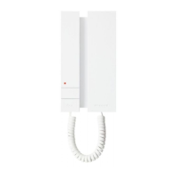
Art. 2608
18
Installing door-entry phone Art. 2608
18
General installation and operating instructions
19
Operating distances table
19
Operation
19
Description of button functions and settings
20
Settings for bracket Art. 5714/K and Style door-entry phone Art. 2608
20
Setting bracket Art. 5714/K as main or secondary
21
Additional main or secondary monitors
21
Selecting the monitor ringtone
21
Using the kit in systems with a main entrance
22
Programming buttons on Art. 4680K
22
Special programming - Art. 4680K
23
Wiring diagrams
BK/018I Basic diagram for two-family kits Art. 8173I with cascade connection. Switching on/voltage check with system in standby.82
BK/013IB Basic diagram for two-family kits Art. 8173I with branch connection 83
BK/014IB Diagram for two-family kits Art. 8173I extended with a second Art. 4879K. Branch connection. 84
BK/014I/A Diagram for two-family kits Art. 8173I extended with a second Art. 4879K. Cascade connection. 85
BK/018I/A Diagram for two-family kit with additional power supply unit Art. 1595 86
BK/019I Use of remote camera module Art. 1259/A 87
BK/EN/109I Diagram for connecting 2 to 9 Bravo Kits to main entrance panel using Art. 4834/9 88
BK/EN/110I Diagram for connecting 30 Bravo Kits (maximum) to the main entrance panel. Cascade connection of Bravo using Art. 1424 90
SB2/AAQ Connection of video amplifi er Art. 4833/A 92
BK/HI Addition of a main monitor in parallel. Cascade connection 92
BK/II Addition of a main monitor in parallel. Branch connection 93
BK/A9 Branch connection of 1 main monitor and 1 secondary monitor with the same user code 93
BK/CI Cascade connection of 1 main monitor and 1 secondary monitor with the same user code 94
BK/AABI Connection of additional door-entry phones with branch connection from monitor 94
BK/AAAI Connection of additional door-entry phones with cascade connection from monitor 95
BK/FI Addition of a parallel door-entry phone, with branch connection from riser 95
PXK/AAK Connection of call repetition devices (Art. 1229 or Art. 1122/A) 96
BK/PI Use for various purposes of button P1 (Art. 5714/K) 97
BK/NI Use of LED 1 97
SB/X3 Use for various purposes of button P1 (Art. 2608) 97
Floor door call connection variant 98
PXK/EC Connecting actuator relay Art. 1256 98
PXK/RTNP Using the external unit relay on lock-release or actuator control (see special programming, page 23: actuator control management) 99
PXK/SNP Variant with security door lock and additional power supply 99
Using the RC network for door lock fi lter on relay contacts 100
PXK/DO Door open indication use variant.
Only for use in systems with a single external unit without switching devices Art. 1224A, Art. 1424.
100
 Loading...