1717
EN
1
2
3
4
5
6
1
2
1
2
3
4
5
6
3 4
1
2
3
4
5
6
3
2
1
5
CV
4
CV
3
D
I
P
140-145 cm
115-125 cm
CV
4
CV
3
D
I
P
1 2 2B2A
1
2
3
4
5
6
10,2cm
11cm
14,4cm
8,1cm 1,4cm
1,4cm
1
1
2
2
3
1
1
2
3
2
1
3
4
5
6
3
4 5
2
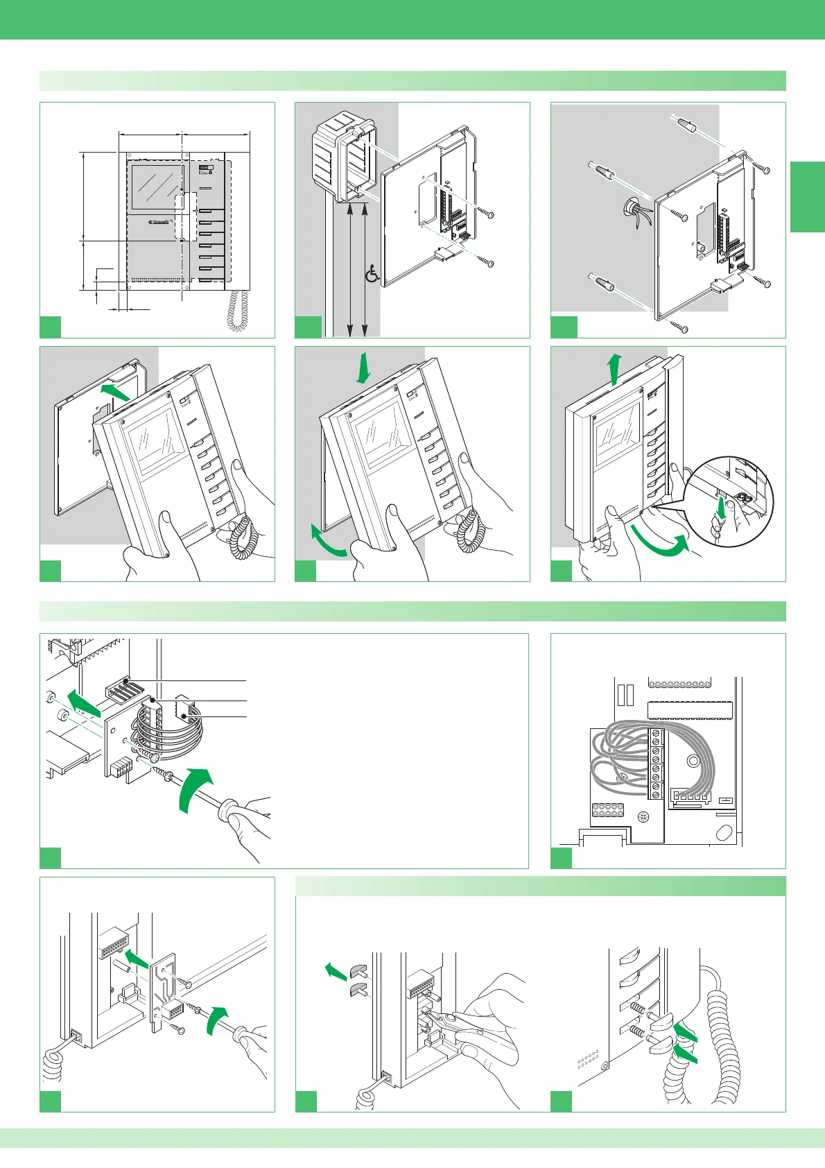
Installing optional card Art. 5733, Art. 5734
1 Bracket male connector
2 Terminal board:
Note: To use the buttons as a C.NO. contact (24 V-100 mA
max.) remove the wire to the bracket connector and free
the corresponding common contact.
P3 monitor button 3 contact
C3 monitor button 3 common contact. Main common
contact from bracket Art. 5714/K (disconnect the wire to
the bracket connector to free all common contacts)
P4 monitor button 4 contact
C4 monitor button 4 common contact
+P5 monitor button 5 contact for Art. 5733. LED 5 positive
input for Art. 5734
-C5 monitor button 5 common contact for Art. 5733. LED 5
negative input for Art. 5734
+P6 monitor button 6 contact for Art. 5733. LED 6 positive
input for Art. 5734
-C6 monitor button 6 common contact for Art. 5733. LED 6
negative input for Art. 5734
3 Female connector Art. 5733, Art. 5734
Installing Art. 5701 as a fl ush- or wall-mounted device
For optional card Art. 5734 only
► Disconnect and remove monitor
buttons 5 and 6
► Fit the transparent buttons supplied
in the packaging into button
positions 5 and 6
► Run the wires between the card and
the bracket
 Loading...