10
INSTALLATION & USE www.comfortcompany.com
INSTALLATION (QUANTUM
®
, PERMOBIL
®
, & ROVI
®
)
The following instructions illustrate the base mounting plate found on each power chair.
WARNING! To prevent injury, damages or voided warranty, DO NOT make any alterations to the equipment. Modications in attempt
to interface with any other products than those listed in this manual potentially compromise the safety of the user and voids warranty.
QUANTUM
®
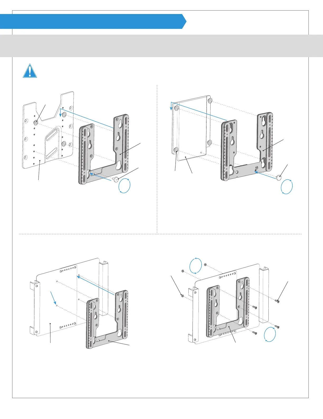
- (No tools required for installation.) PERMOBIL
®
- (No tools required for installation.)
4
4
5
5
3
Remove threaded knob F from base mounting plate G.
4
Line up three pegs H with mounting bracket B and slide
it down on the pegs.
5
Insert threaded knob F and tighten to secure.
Skip to Step 7 on page 12
3
Remove threaded knob F from base mounting plate G.
4
Line up four pegs H with mounting bracket B and slide it
down on the pegs.
5
Insert threaded knob F and tighten to secure.
Skip to Step 7 on page 12
G
G
H
H
F
B
B
F
ROVI
®
- (Allen wrench, 10mm wrench and drill with ¼“ drill bit are required for installation. Allen wrench is provided.)
3
4
5
5
3
Line up the back support against base mounting plate G where desired and mark the location of the four counter-
sunk holes on mounting bracket B.
4
Ensure that holes are level and then drill four ¼” holes in base mounting plate G where marked.
5
Use longer at head screws J provided and lock nuts K and fasten using allen wrench and 10mm wrench.
Skip to Step 7 on page 12
J
K
G B B
*Note: A Recessed Planar Interface Plate must be installed on the chair and will be referred to as a base mounting plate for the purpose
of these instructions. Please refer to the literature provided with chair for installation of Recessed Planar Interface Plate if needed.