8
INSTALLATION & USE www.comfortcompany.com
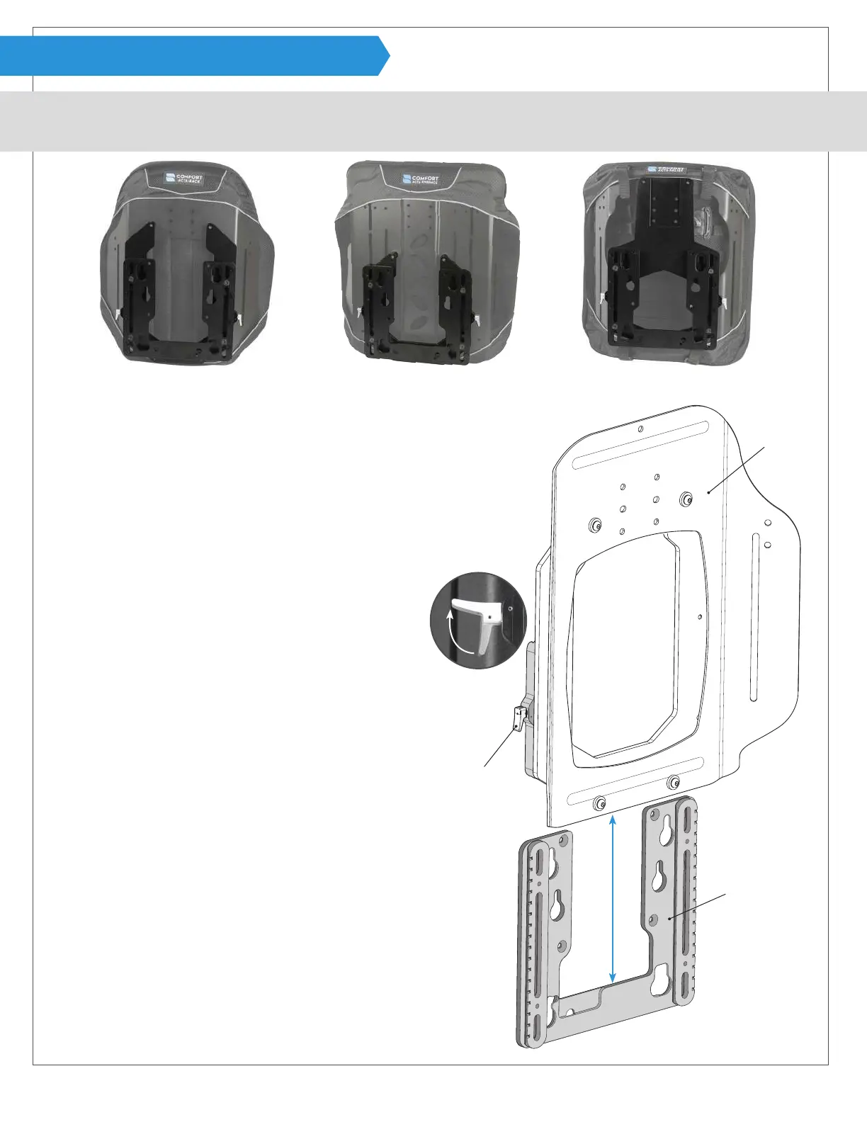
INSTALLATION (PRE-ASSEMBLED)
Use the following instructions if Compass
®
Power Mount Hardware is already assembled and attached to the back support.
For all Acta-Series back supports.
2
A
B
Acta-Back
®
shell shown
C
1
Start by ipping release levers A out on both sides of the
hardware assembly to release mounting bracket B.
Note: Support the mounting bracket while releasing because
it should slide easily and will drop.
2
Slide mounting bracket B down and set back support C with
the remaining hardware aside. See next page to verify orien-
tation of mounting bracket B and make sure it is set up for
installation on the desired power chair.
1
Note: Back support
shell shown without
a cover for visual.
Cover should be on
back support during
installation.
Compass
®
Power Mount Hardware will most often come pre-assembled
and attached to the back support ready for use with the chair designated
during the ordering process. In the event it is not ready for installation for
any of the reasons listed below, please refer to a related section before
going through this installation process.
· Hardware Assembly is not attached to a back support
Page
- Acta-Relief™ 14
- Acta-Back
®
or Acta-Embrace
®
16
· Hardware is not congured for the power chair needed
- Mounting Bracket & Male Track 9
· Requires posterior depth adjustments-
- Shell Spacers - Acta-Relief™ 14
- Head Support Track Spacer- Acta-Relief™ 15
· Parts are being replaced
- Male Track - Mounting Bracket. 9
- Female Track - Shell Bracket- Acta-Relief™ 15
- Female Track - Shell Bracket- Acta-Back
®
or Acta-Embrace
®
16
- Shell Spacers- Acta-Relief™ 14
- Shell Spacers- Acta-Back
®
or Acta-Embrace
®
16
· Hardware has binding issues.
- Cleaning and Lubrication 17
- Track alignment 17