14
SET UP & ADJUSTMENTS www.comfortcompany.com
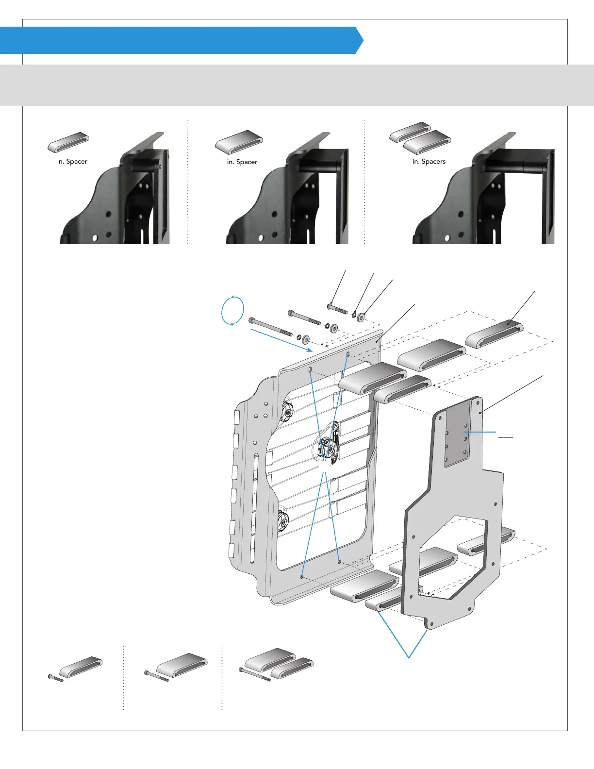
ASSEMBLY (ACTA-RELIEF™ SHELL SPACERS)
For Acta-Relief™ & Acta-Relief™ LTS. Compass
®
Power Mount Hardware requires a certain cover style for the back support. If converting a
back support from manual chair hardware to Compass
®
Power Mount Hardware, contact Customer Service for the correct cover.
A
B
C
D
F
E
1 + 2 in. Spacers
2 in. Spacer
1 in. Spacer
40 mm button head bolt A
1 inch shell spacer E
65 mm socket head bolt A
2 inch shell spacer E
90 mm socket head bolt A
1 & 2 inch shell spacers E
1
2
3
A
A
A
E
E
E
Attaching shell bracket and
spacers to the back support:
Acta-Relief™ shell
without cover shown
1
Remove back support cover and
locate the four holes on shell D for
attaching power mount hardware.
If already assembled, unscrew four
bolts A to use alternate spacers.
2
Line up bolt A, safety washer B, at
washer C, back support shell D, and
spacer E with shell bracket F.
Note: Bolt A and spacer E will vary
depending on the desired congu-
ration. Use longer bolts with deeper
spacers (see below).
3
Lightly fasten and continue with the
other three holes using allen wrench
provided. Tighten fully after all points
are attached.
4
Replace cover on back support.
Note: The head
support relief cutout
must face away from
the back support.
Note: The contoured shell spacer
face will match the rounded
corners of the shell bracket.
Standard ACTA-RELIEF™ conguration
2 in. (5.1 cm) SDU 3 in. (7.6 cm) SDU 4 in. (10.2 cm) SDU