9
INSTALLATION & USE
MOUNTING BRACKET & TRACK ALIGNMENT
Use the following instructions to verify and/or switch mounting bracket orientation or replace the mounting bracket and male track parts.
E
D
B
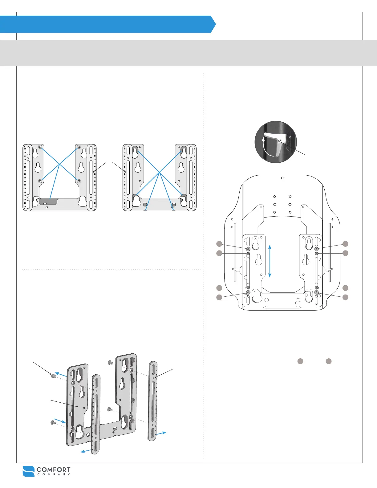
Note: Notches on the
male track point out and
away from each other.
The mounting bracket (pictured below) should be set up for the power
chair selected when ordered. However, if needed, the mounting bracket
can be switched to accommodate a different chair at any time.
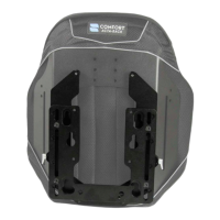
To identify which chair the mounting bracket is set up for, look for male
track pieces which feature notches. The side the tracks sit on will deter-
mine which chair it works with.
SIDE A
QUANTUM
®
, QUICKIE
®
& ROVI
®
PERMOBIL
®
ONLY
SIDE B
SIDE A features 4 countersunk
holes and a large relief cutout.
SIDE B features relief cutouts
around 4 peg holes and along
the bottom edge of the bracket.
MALE
TRACKS
If the mounting bracket is set up for the desired chair, skip to Step 3
on page 10 or 11. If the mounting bracket needs switching, proceed
with steps 3a - 8a below.
To adjust the mounting bracket:
To check track alignment:
6a
Check for track alignment by sliding the male tracks
into the female tracks of the hardware assembly with
both release levers A in the open position. It should
slide up and down easily.
7a
If the tracks seem to bind, there is access to eight
screws in the track assembly from the rear face.
Gently loosen all eight screws.
8a
For best results, tighten screws
1
through
8
in the
order shown above. Repeat steps until the assembly
slides easily and then continue with installation on
the next page.
See the “Hardware Cleaning & Alignment” section
on page 17 if needed for additional instructions on
cleaning and lubricating track pieces.
6a
3a
5a
4a
4a
1 3
8 6
5 7
4 2
3a
From the back side of mounting bracket B, unscrew four at head
screws E with the allen wrench provided.
4a
Move male tracks D to the opposite side of the mounting bracket.
Note: notches on the male track must be visible and run along the
outer edge of the mounting bracket.
5a
Reassemble mounting bracket B and male tracks D using screws
E. Note: It is important to tighten the screws evenly for the best
alignment.
6a
A