16
SET UP & ADJUSTMENTS www.comfortcompany.com
Use the following instructions if Compass
®
Power Mount Hardware is not already assembled and attached to the back support.
Compass
®
Power Mount Hardware requires a certain cover style for the back support. If converting a back support from manual
chair hardware to Compass
®
Power Mount Hardware, contact Customer Service for the correct cover.
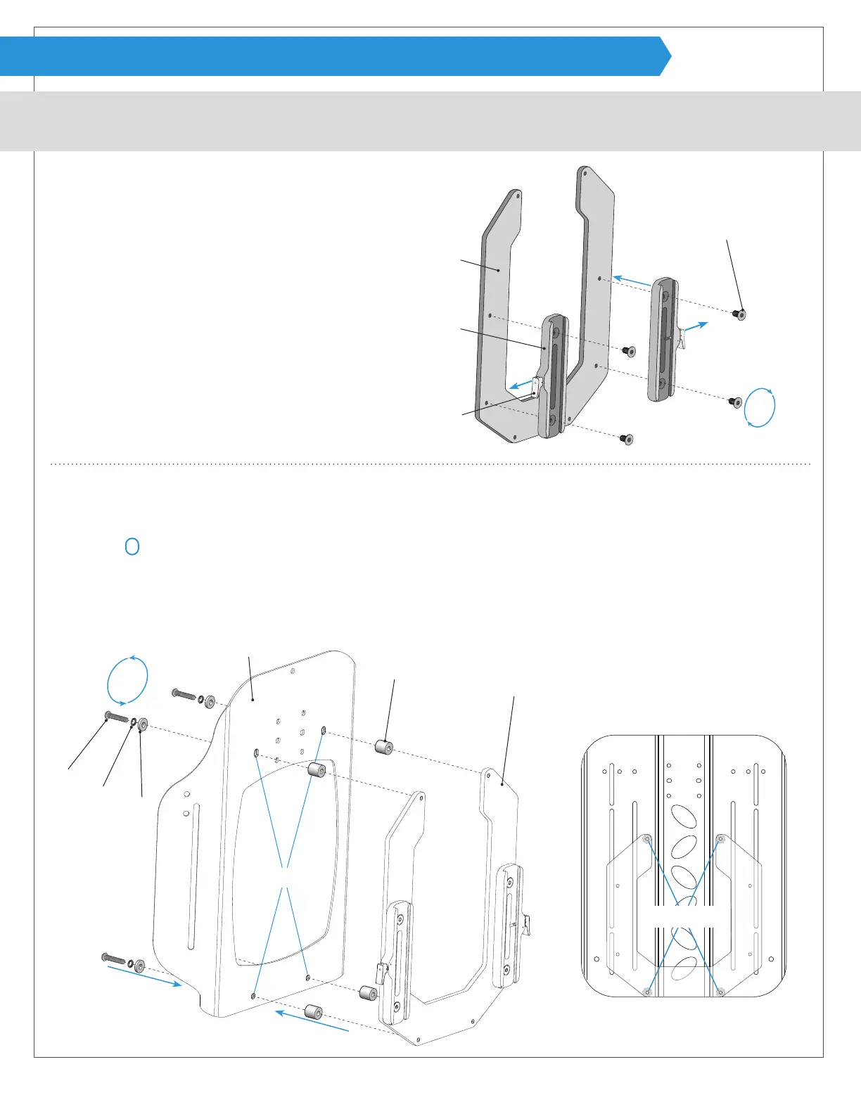
Attaching female tracks to the shell bracket:
Attaching shell bracket to the back support:
2
Acta-Embrace
®
Shell Holes
Acta-Back
®
shell without cover shown
Rear view Acta-Embrace
®
shell
1
Remove cover and locate the four holes on back support shell E for attaching power mount hardware. Note: Acta-Back
®
and
Acta-Embrace
®
shells have two round holes located near the bottom edge of the shell and the top two holes are vertical
oblong
holes.
2
Line up bolt F, safety washer G, at washer H, back support shell E, and spacer J, with shell bracket A.
3
Lightly fasten using allen wrench provided and continue with the other three holes. Tighten fully after all points are attached.
1
Line up holes on shell bracket A with female track B with
the release levers C pointing out and away from each
other.
2
Fasten using screws D. Note: It is important to tighten
the screws evenly for the best alignment.
After attaching tracks to the shell bracket, always check
for alignment with the mounting bracket as outlined on
page 17.
J
E
G
F
H
A
3
1
2
C
B
A
D
ASSEMBLY (ACTA-BACK
®
& ACTA-EMBRACE
®
SHELL BRACKET)
1
1
1
2