15
SET UP & ADJUSTMENTS
ASSEMBLY (ACTA-RELIEF™ SHELL BRACKET & TRACK SPACER)
For Acta-Relief™ & Acta-Relief™ LTS.
Track spacers for Compass
®
Power Mount Hardware are to be used on Acta-Relief™ only when using a head support and additional
clearance is needed. Please refer to the instructions provided with the head support for installation of head support and hardware.
1
1
1
2
1
1
1
2
Acta-Relief™ with
BodiLink™ Head Support
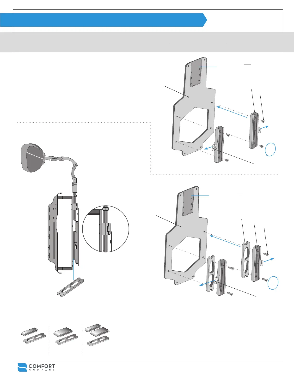
Attaching female tracks to the shell bracket:
Adding track spacers* to the shell bracket:
1
Line up holes on shell bracket A with female track B with the
release levers C pointing out and away from each other.
2
Fasten using at head screws D. Note: It is important to
tighten the screws evenly for the best alignment.
After attaching tracks to the shell bracket, always check for
alignment with the mounting bracket as outlined on page 17.
1
Line up holes on shell bracket A with track spacer E and female track B
with the release levers C pointing out and away from each other.
2
Fasten using alternate at head screws F provided. Note: It is important to
tighten the screws evenly for the best alignment.
After attaching tracks or adding track spacers to the shell bracket, always
check for alignment with the mounting bracket as outlined on page 17.
C
C
A
A
D
F
E
B
B
Note: The tracks must be attached
to the side of the shell bracket with
the head support relief cutout.
Note: The tracks must be attached
to the side of the shell bracket with
the head support relief cutout.
*If using a head support, track spacers may be
required for clearance. All parts, fasteners and
tools required to adjust spacing are provided.
1 in. Spacer
+ Track Spacer
2 in. Spacer
+ Track Spacer
1 & 2 in. Spacers
+ Track Spacer
Possible spacer congurations:
Track spacers use .356” (9 mm) of seat depth
2.356 in.
6.0 cm
3.356 in.
8.5 cm
Total Seat Depth Used
4.356 in.
11.1 cm