12
SET UP & ADJUSTMENTS www.comfortcompany.com
QUANTUM
®
WITHOUT RECLINE
QUANTUM
®
WITH RECLINE
Recommended
BACK GAP = 3”
(7.6 cm)
Recommended
BACK GAP = 7”
(17.8 cm)
QUICKIE
®
PERMOBIL
®
Recommended
BACK GAP = 7”
(17.8 cm)
Recommended
BACK GAP = 6”
(15.2 cm)
ROVI
®
RECLINE SYSTEMS
ROVI
®
TILT SYSTEMS
Recommended
BACK GAP = 6”
(15.2 cm)
Recommended
BACK GAP = 4”
(10.2 cm)
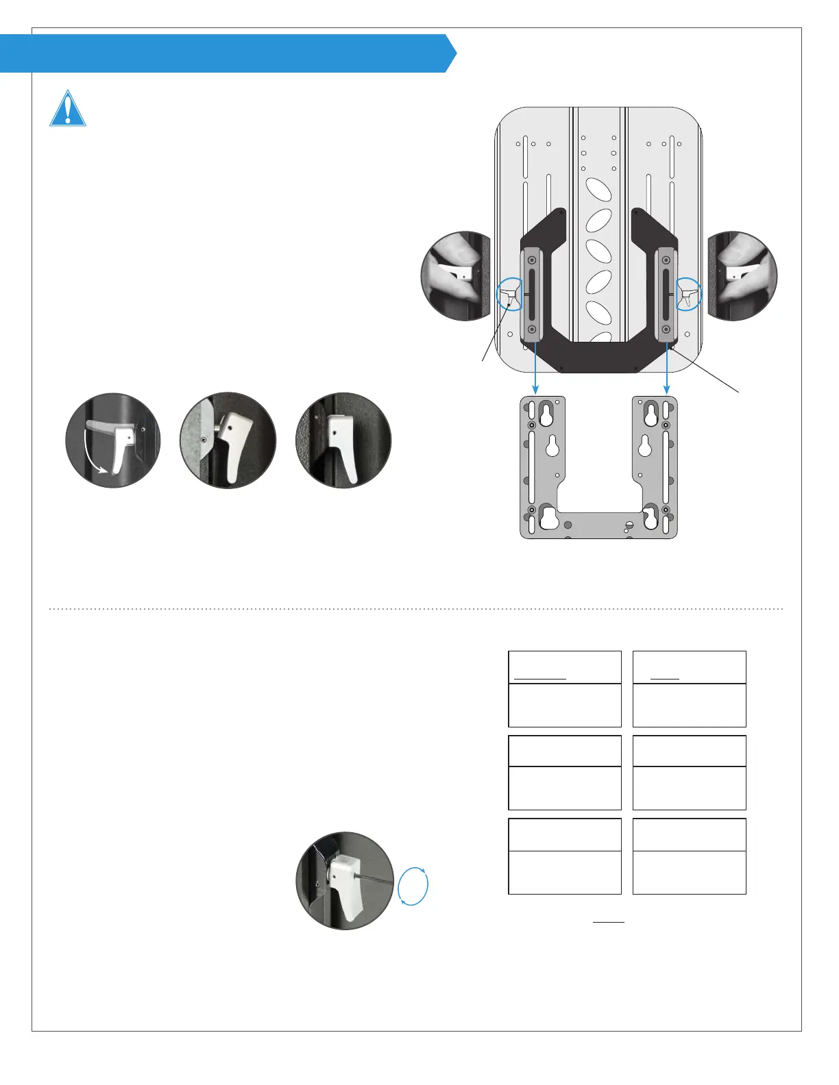
INSTALLATION (BACK SUPPORT ASSEMBLY)
BACK GAP = Manufacturer recommended dimension
from seat base to bottom edge of the back support.
Refer to page 6 for full back gap and height details.
7
From behind the chair, hold the back support and hardware
assembly on each side at the release levers A with them in
the open position as shown. **Note: Holding it this way
allows for the back support to be lowered evenly for better
alignment.
8
Line up female tracks P with the male tracks (not shown) on
the mounting bracket installed on the chair and slide the
assembly down.
9
Once the back support is around the desired position, low-
er the release levers to a closed position. The levers will
click when they are locked into position.
Each chair manufacturer has a suggested “back gap” for setting the height of
the back support on the chair. Please see the height recommendations and then
evaluate the patient needs to set a nal back support height. The patient may
be seated during step 10.
10
Flip release levers A open to slide the back support up or down to
the desired height. Close the levers to set.
11
WARNING! To prevent injury or damage, it is important to run
the chair through its full range of articulation at this point to check
for any possible interference or unwanted movement of seating
components.
12
To lock the release levers in the
closed position, turn the set screw on
the release levers until it makes con-
tact using the allen wrench provided.
If a lever has not fully engaged as shown above (center),
simply shift the back support assembly slightly up or down
until the lever clicks into place as shown on the right.
When not locked, the set screw should be ush with the top
surface of the release lever. Do not remove the set screw.
Installing the back support assembly:
Setting the back support height:
P
A
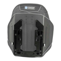
Acta-Embrace
®
without cover shown (rear view)
Base mounting plate
and chair not pictured
Not fully engaged
Completely engaged
8
7**
9
12
WARNING! DO NOT allow for wires or other components
to run through the support/hardware system at any time.
If tracks appear to be misaligned or binding occurs, please refer
to “Hardware Cleaning and Alignment” section on page 17.