Appendix E.User Interface
Connections
E.1 User Interface Connections
Supplied mating connectors can be used, but are not required. Refer to section 5 for pin out
definitions.
Connector Kit part numbers:
Radyne P/N Description Connector Location
1. CA/3446-9 RS530 Ribbon cable J2
2. CNRSHUNT Shorting/default plug JP5 & JP6
3. CNR102387-1 Dual Row header 10 Pin J1
4. CNR102387-6 Dual Row Header 26 Pin J2
5. TMR102548-6 Receptacle Contacts J1 & J2
6. CNR09-50-3041 Conn Crimp 4 Terminal Housing J3 & J7
7. TMR08-56-0106 Terminal crimp 18-24AWG for 2139 J3 & J7
J1 & J2 Interface Connectors located on PCB
J1: Async Interface Connector - 10Pin Dual Row: Mfg (Samtec) P/N: TSW-1-05-7-G-D
J2: Mil 188-114A Connector - 26Pin Dual Row: Mfg (Samtec) P/N: TSW-1-13-7-G-D
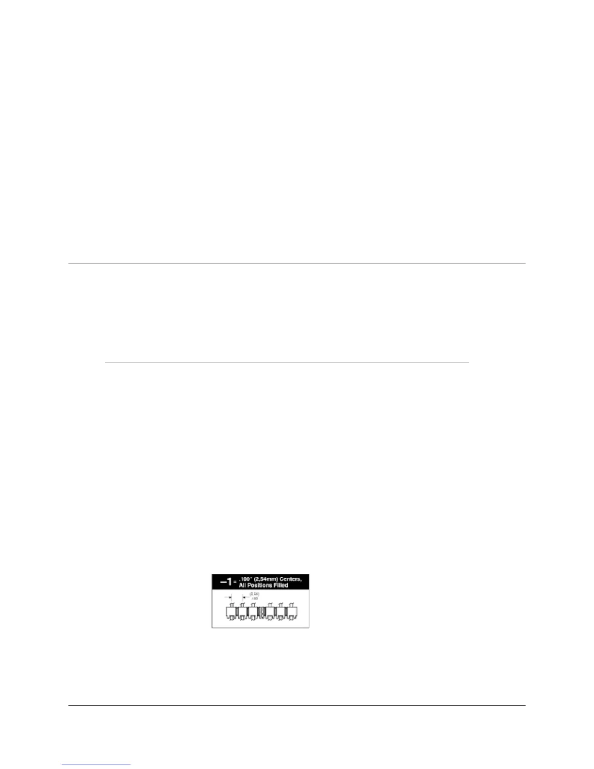
MFG: Samtec connector information
TSW = Terminal strip series
-1 = .100” Centers
05 or 13 = Number of pins per row
7 = Straight pin version dimensions
MN-DMD1050 E–1
Revision 9