Chapter 3. Theory of Operation
3.1 DMD1050 Hardware
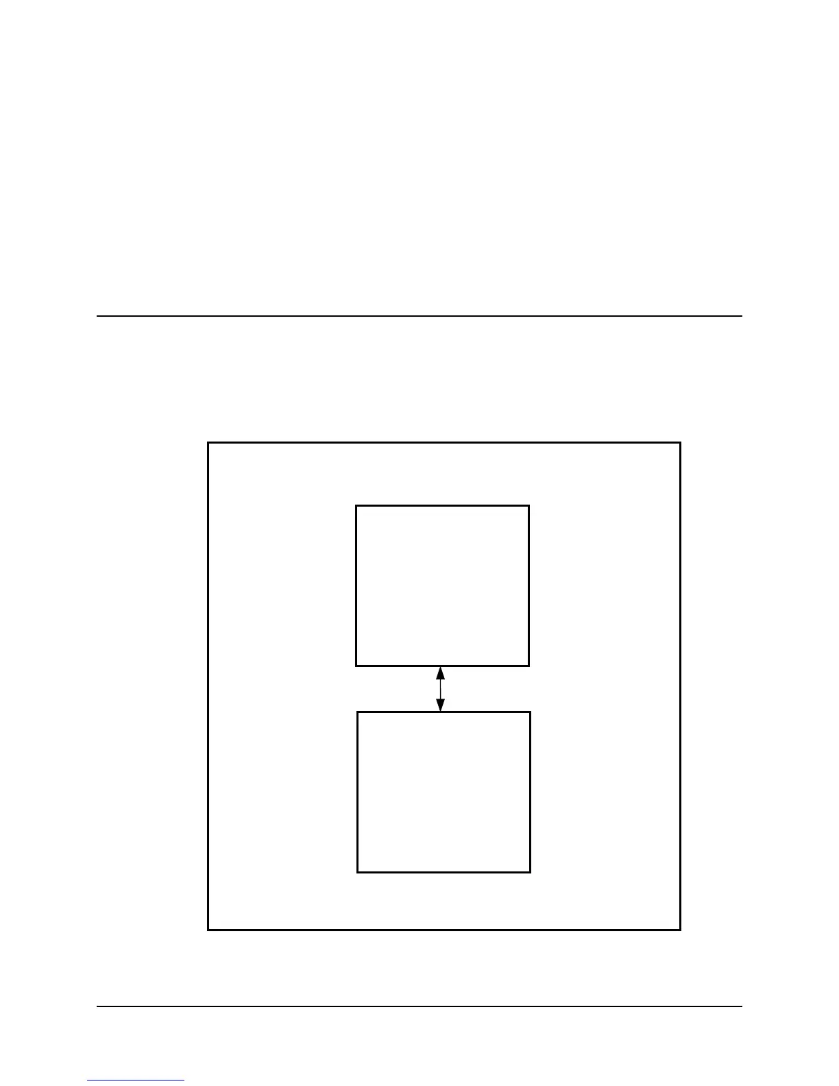
The DMD1050 is based on a two printed circuit card design. The standard configuration consists
of an L-Band Assembly and a Digital Baseband Assembly. This configuration includes built in
Data interfaces and a number of different software upgrade options. A block diagram of the
DMD1050E is shown in Figure 3-1.
L-Band
IF
Card
Digital
Baseban
Car
( Interface & Turbo )
Cable
Figure 3-1. DMD1050 Block Diagram
MN-DMD1050 3–1
Revision 9