4-3
4.5.4 RF Leakage Measurement
NOTE: To ensure accuracy when making leak-
age measurements, perform all leakage testing
using methods and instruments that are com-
pliant with the prcedures outlined in Section
19 of IEC60601-2-2 (Particular Requirements
for the Safety of High Frequency Surgical
Equipment).
RF Leakage can present a hazard in the operating
room because electrosurgical currents can flow
to the patient and operating room staff through
unintended paths, which can cause injury. RF
leakage occurs because the total energy in the
output voltage waveform is provided with a con-
ductive path through stray parasitic capacitance
distributed within the generator and along the
length of the leads.
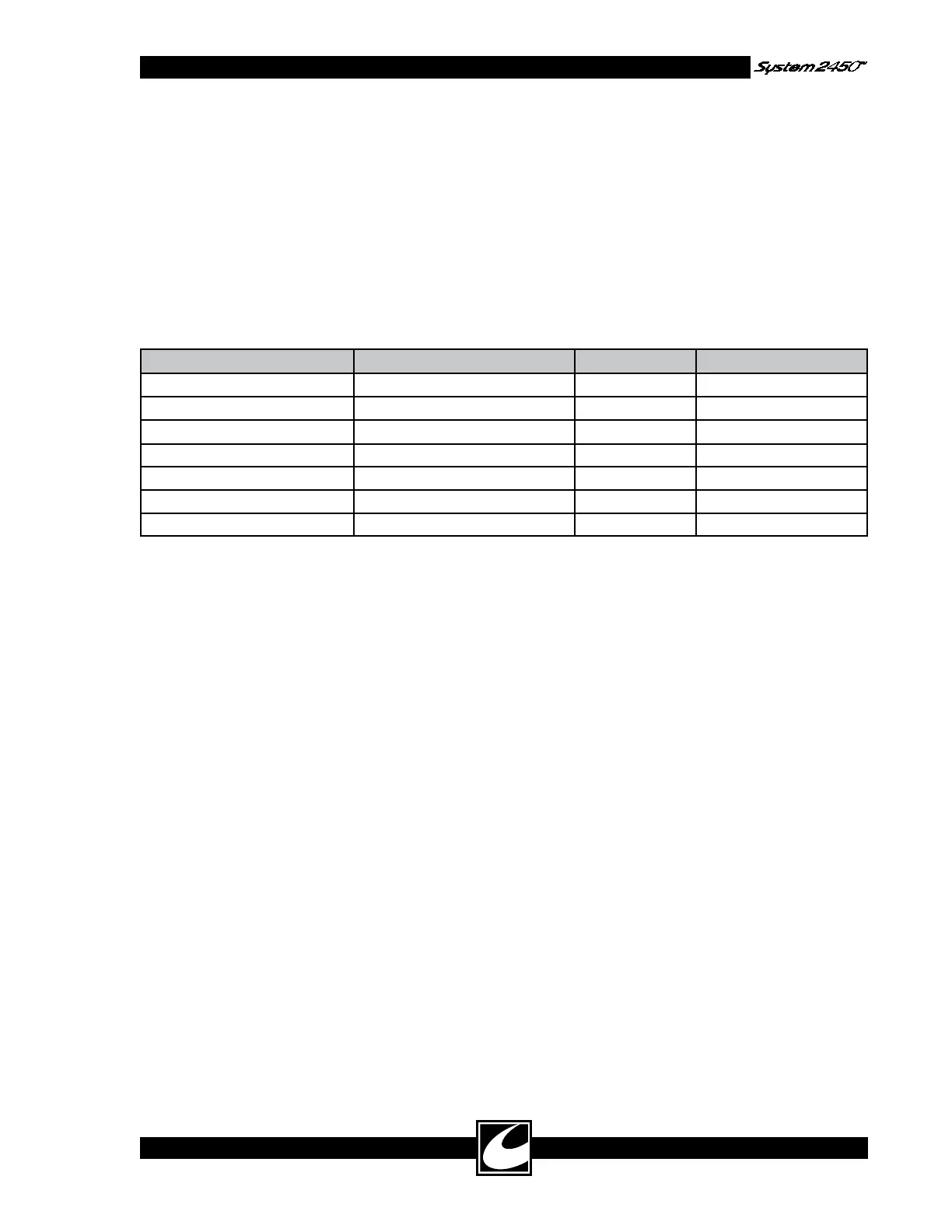
Table 4.4 presents the allowed RF leakage currents
to ground.
Table 4.4 Allowable RF Leakage Current to Ground
MEASURED TERMINAL ACTIVATED ACCESSORY MODE RF LEAKAGE (Ma)
Dispersive Electrode Coag Combination Monopolar Standard Coag < 100
Dispersive Electrode Cut Combination Monopolar Pure Cut < 100
Dispersive Electrode Hand Controlled Standard Coag < 100
Combination Monopolar Active Coag Combination Monopolar Standard Coag < 100
Hand Controlled Active Left Hand Controlled Standard Coag < 100
Bipolar Right Bipolar Footswitch Bipolar Macro < 67
Bipolar Left Bipolar Footswitch Bipolar Macro < 67
Equipment:
• ESU Tester with RF Leakage function -OR-
• 0-250 is RF Ammeter with a 200 ohm 10 W
Non-inductive Resistor
• Patient Plate Adapter Plug
• 2 - Test leads, 1 m max. Length
• 3 - Test leads, 10 cm max. Length
• Wooden table approximately 1 m from floor.
NOTE: Use a measuring device that meets IEC
specification for RMS measured over one second.
Procedure:
1) Ensure that the unit is fully assembled and all
fasteners are tight.
2) Place the ESU tester or meter with resistor on
the table so that they are at least 0.5m away
from the unit under test and any other con-
ductive surface.
3) Set the unit for full power for the modes
noted in the table. Connect the ESU tes-
ter in accordance with the manufacturer’s
instructions -OR- connect the 200-ohm non-
inductive resistor in series with the 250 mA
RF ammeter to the Equipotential Ground
Connection on the Rear Panel. Also make
sure there are no connections to any output
other than the one you are measuring.
WARNING: HAND CONTROL ACTIVA-
TIONS SHOULD BE KEYED USING
3” OR LESS WELL-INSULATED
JUMPER. USE OF AN INSULATING
ROD TO INSERT THE JUMPER IS
ADVISED TO PREVENT RF BURNS.
3) One at a time, connect test setup to each RF
output terminal indicated in Table 4.4 and
activate the unit using the corresponding
command. Confirm no meter readings exceed
the specified maximum. Hand controlled
Coag activations are accomplished by con-
necting a jumper between the left jack and
center jack of the desired hand switched acces-
sory jack.
RF leakage should also be measured between inac-
tive outputs and the Dispersive Electrode connec-
tion. The procedure is as follows:
1) Set the unit for full power for the modes
noted in Table 4.5. Connect the ESU tes-
ter according to manufacturer’s instructions
- OR- the 200-ohm non-inductive resistor in
series with the 250 mA RF ammeter to the
Dispersive Electrode connection on the front
panel. Also make sure there are no connec-
tions to any output other than the one you
are measuring.