4-5
5) Since the System 2450 monopolar active out-
puts are disconnected by relays when the unit
is not activated, active-to-neutral leakage tests
must be performed with the unit activated in
order to be valid.
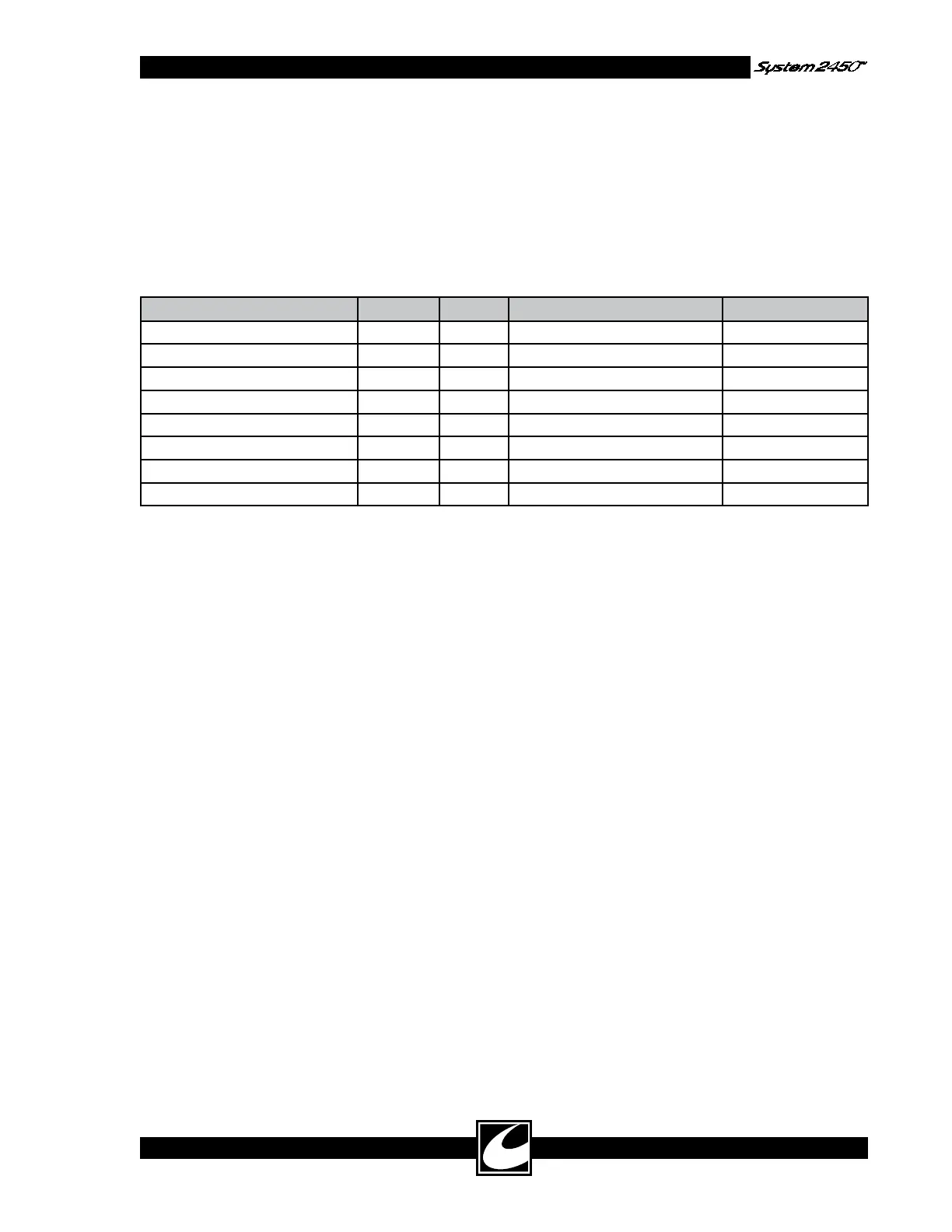
6) With all power controls set to zero, measure
the leakage current as in step 1 from each of
the three active output terminals to neutral;
see Table 4.8; while that output is activated
in Cut by the appropriate footswitch or hand
control jumper. Hand control cut activations
are accomplished by connecting a jumper
between the two outer jacks of where the
handcontrolled accessory is plugged into the
unit.
Table 4.8 Line Frequency Allowable Leakage - Active
RF output to Neutral LINE GND ACTIVATION LIMIT max
Combination Monopolar Active Normal Closed Combination Monopolar Cut 15 µA
Combination Monopolar Active Reversed Closed Combination Monopolar Cut 15 µA
Combination Monopolar Active Normal Open Combination Monopolar Cut 15 µA
Combination Monopolar Active Reversed Open Combination Monopolar Cut 15 µA
Hand Controlled Active Normal Closed Hand Controlled Cut 15 µA
Hand Controlled Active Reversed Closed Hand Controlled Cut 15 µA
Hand Controlled Active Normal Open Hand Controlled Cut 15 µA
Hand Controlled Active Reversed Open Hand Controlled Cut 15 µA
4.5.6 Automatic Return Monitor (A.R.M.)
Check
A.R.M. has two specific ranges that will be tested
initially and then the circuit will be tested to verify
that the circuit measures dispersive electrode resis-
tance correctly. For this testing, only a Decade
Resistance Box (DRB) and a dispersive electrode
cable adapter are required. Connect the DRB to
the Dispersive Electrode Receptacle using the dis-
persive electrode cable adapter.
A.R.M. may be reset by disconnecting the dis-
persive electrode connector or adjusting the DRB
above 10K Ohms until the Single and Dual
Dispersive Electrode Status/Alarm Indicators flash
red in alternating fashion. Allow approximately
two seconds after the DRB is changed before pro-
ceeding to the next step in the procedure. A.R.M.
indicators not mentioned in the procedure must
be off for each test.
1) Dual Electrode Alarm Limit: Set the DRB to
158 Ohms, then connect it to the Dispersive
Electrode Receptacle and verify that the
Single and Dual Dispersive Electrode Status/
Alarm Indicators flash red in alternating fash-
ion.
2) Dual Electrode Upper Limit: Set DRB to
140 Ohms and verify that the Dual Dispersive
Electrode Status/Alarm Indicator is Green.
3) Dual Electrode Lower Limit: Set the DRB
to 15 Ohms and verify the Dual Dispersive
Electrode Status/Alarm Indicator is Green.
4) Single Electrode Upper Limit: Set the DRB
to 7 Ohms, then reset A.R.M. and verify the
Single Dispersive Electrode Status/Alarm
Indicator is Green.
4.5.7 Output Coupling Capacitor Check
WARNING: ENSURE ALL POWER
SETTINGS ARE AT 0 WATTS BEFORE
CONDUCTING THIS TEST TO PREVENT
INJURY TO PERSONNEL AND DAMAGE
TO TEST EQUIPMENT.
NOTE: Not all capacitance meters will read prop-
erly for this test. The test frequency should be at
or below 1 kHz for best accuracy. The following
meters have been tried successfully: Fluke 189,
Extech 285, Sencor LC75 and HP4284A (1 kHz
setting or below).
1) Connect shorting plug to banana adapter to
the two pin Dispersive Electrode Receptacle.
Use 6” or shorter test leads to connect a
capacitance meter between the shorting plug
adapter and the footswitched ReadiPlug
Universal Accessory Receptacle.
2) Measure capacitance and confirm it is less
than 0.2 nF.