Reinstall
these two
screws first
4-17
5) Disconnect display flex connector, being care-
ful not to damage it.
Control/Display Board Replacement:
1) Connect display flex connector and place
board back onto threaded standoffs.
2) Replace aluminum standoff in its previous
location and tighten all hex standoffs.
NOTE: The aluminum standoff provides a
ground and must be located as shown below.
3) Connect ribbon cable.
4) Replace sheet metal shield and tighten six
screws into hex standoffs.
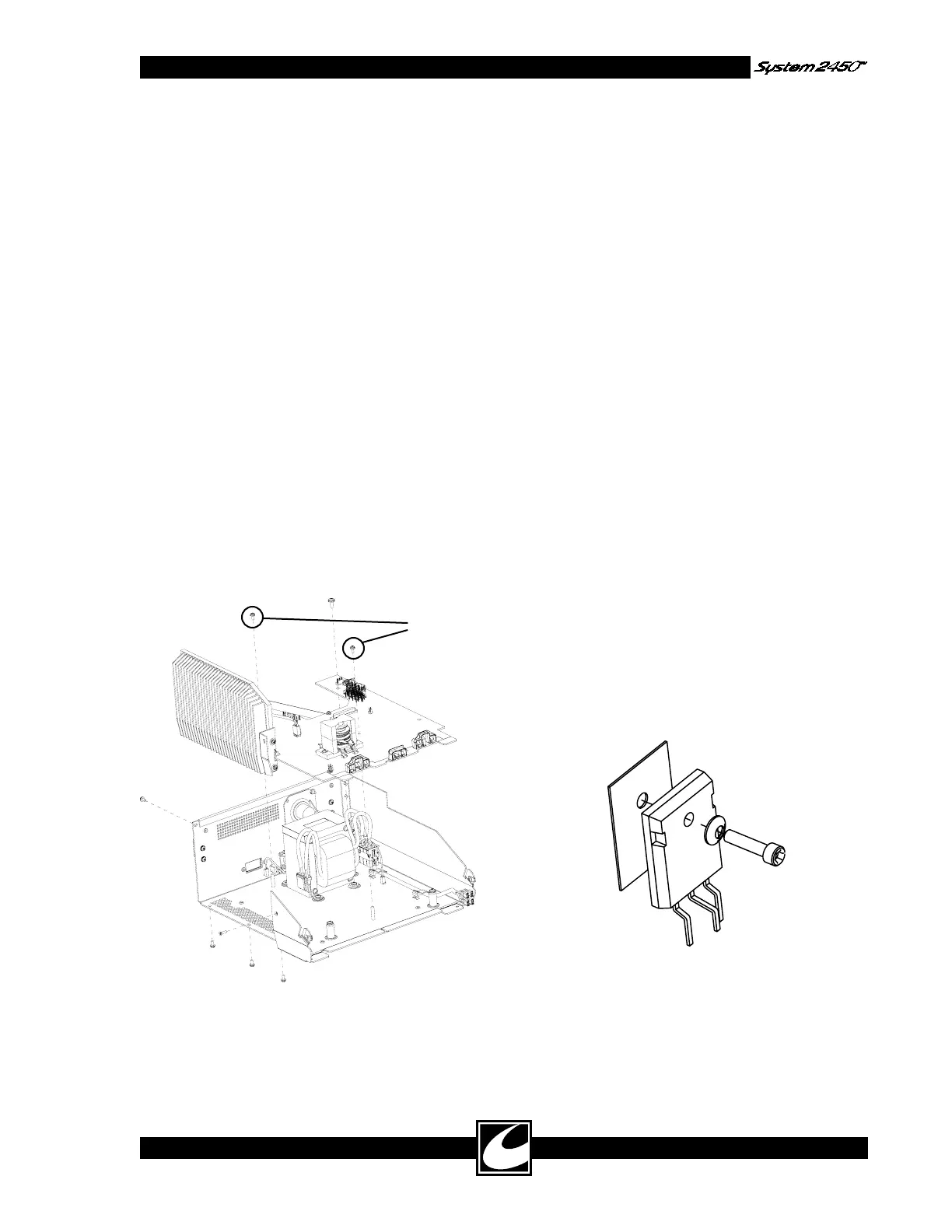
4.12.4 Power Board Removal & Replacement
Power Board Removal:
1) Remove Top.
2) Remove Bezel.
3) Remove the five screws mounted to the heat
sink in the rear, bottom and side of chassis.
4) Remove the five screws mounted to the chas-
sis standoffs. Do not remove the screws that
secure the angle bracket between the Power
PWB and the heat sink.
Power Board Replacement:
1) Reverse board removal operation.
NOTE: Install the noted two, smaller screws
first, to assure Power Board alignment in
chassis.
4.12.5 Power Transistor Replacement
CAUTION: This device contains components
that can be damaged by static electricity. Proper
handling by grounding of personnel during servic-
ing is mandatory.
All Power Board components mounted to the heat
sink may be replaced. Use only components sup-
plied by CONMED.
Follow these instructions for replacement:
1) No thermal compound is necessary, but the
mating surfaces of the transistor, insulator
pad and surface of heat sink should be clean.
Always replace the insulator pad associated
with the transistor. Always fasten or clamp
the part to the heat sink surface prior to sol-
dering it to the board. This will assure good
thermal contact is maintained.
2) In order to maintain alignment with the heat
sink surface, the leads of these parts have been
bent to the proper shape. They should be
purchased from CONMED with bent leads.
3) When installing these parts, be sure to orient
the Bellville washer as shown, with the convex
surface next to the head of the screw. Tighten
screws to 5-7 inch pounds.
5) Disconnect all cable connectors – Transformer,
speaker, footswitch, AC power, and 3.5mm
jack.
6) Pull board slightly forward to remove it from
the chassis.