3-1
Theory of Operation
Section 3.0
System 2450™ functions and essential circuit information are provided in this section. This section begins
with a description of the key parameters for each mode. This is followed by an overview of how the system
functions and some key operational information for the modules within the system.
3.1 Mode Descriptions
The key functional parameters for each mode are presented here. Nominal mode specifications are provided
in section 1.2.11 of the System 2450 Operators Manual.
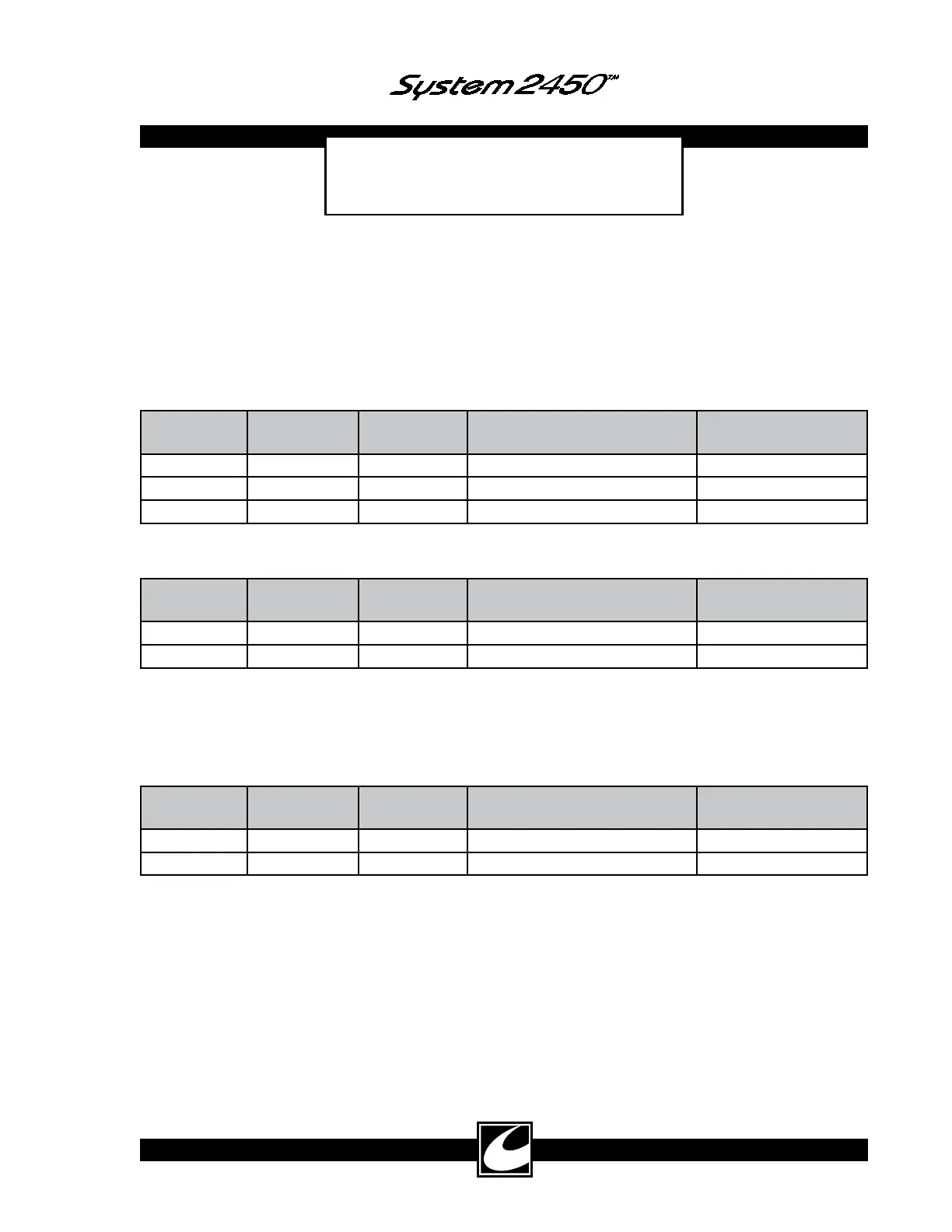
3.1.1 Cut Major Modes
Major Mode Minor Mode Nominal RF
Frequency
Modulation (Number of
Pulses, Nominal Time On/Off
Modulation (Normal
Frequency & Period)
Cut Pure 400 KHz None None
Blend 400 KHz 11 pulses, 28µs / 12µs 25 KHz / 40µs
Hi Blend* 400 KHz 9 pulses, 23µs / 17µs 25 KHz / 40µs
*Hi Blend can be set by a Hospital Qualified Biomedical Technician – see Section 4.8.
3.1.2 Coag Major Modes
Major Mode Minor Mode Nominal RF
Frequency
Modulation (Number of
Pulses, Nominal Time On/Off
Modulation (Normal
Frequency & Period)
Coag Standard 495 KHz Single pulse 40 KHz / 25µs
Spray 495 KHz Single pulse 20 KHz / 50µs
Standard and Spray Coag modes are fundamentally different from the Cut modes in that the resonant circuit
of the RF Amplifier and Transformer combination is excited by the energy of a single pulse, causing the reso-
nant circuit to ring until the energy is dissipated. Spray Coag provides the maximum open circuit voltage for
which the system is rated.
3.1.3 Bipolar Major Modes
Major Mode Minor Mode Nominal RF
Frequency
Modulation (Number of
Pulses, Nominal Time On/Off
Modulation (Normal
Frequency & Period)
Bipolar Macro 400 KHz None None
Micro 400 KHz None None
3.2 System Overview
Mains power is converted to electrosurgical output power through the RF Power Supply (RFPS), the RF
Amplifier, and the Transformer and Output sections of the system.
Mains power is converted to high voltage direct current power in the RFPS to supply the RF Amplifier.
This is essentially a power transformer with a power factor corrected regulator. The power factor correction
can be enabled or disabled under software control.
Pulses generated in the RF Controller are amplified to electrosurgical power and voltage levels in the RF
Amplifier and Transformer portions of the power train. Three high-voltage bipolar transistors and a single
MOSFET make up the hybrid-cascode RF Amplifier. The hybrid-cascode amplifier is a fast, high-voltage
amplifier that can be controlled by the combination of DC voltage (VBASE_PWM) and a fixed amplitude,