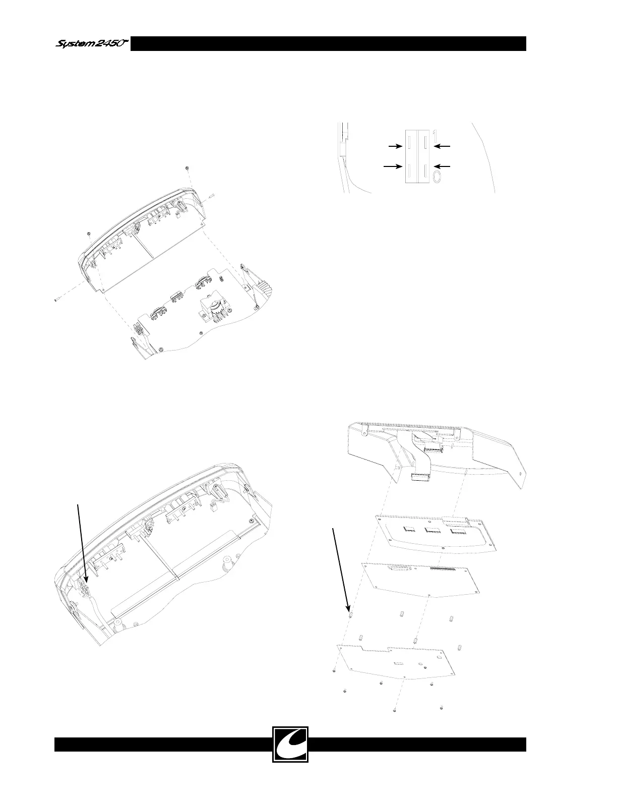
Power Switch
Connectors
White
Blue
Black
Brown
This standoff
must be
aluminum
4-16
4.12.2 Bezel Removal & Replacement
Bezel Removal:
1) Remove Top.
2) Remove two flat-head screws on side of bezel
and two pan-head screws on bottom of bezel
as shown.
3) Unlatch dispersive electrode connector.
4) In most situations, it is not necessary to
remove the four power switch connectors.
The bezel can be rotated off to the right side
for power board removal. To fully remove
the bezel, these connectors must be discon-
nected.
Bezel Replacement:
1) Connect power switch connectors as shown,
if required.
2) Connect dispersive electrode connector.
3) Align bezel between chassis flanges and center
slot. Slide bezel into unit as shown in figure.
4) Replace and tighten screws.
4.12.3 Control/Display Board Removal &
Replacement
Control/Display Board Removal:
1) Remove Top.
2) Remove the six screws and remove sheet
metal shield.
3) Disconnect the ribbon cable.
4) Remove the one aluminum and five plastic
hex standoffs, noting location of aluminum
standoff. Lift board off the threaded stand-
offs.