3. Outside Dimensions and Part Names
User’s Manual
17
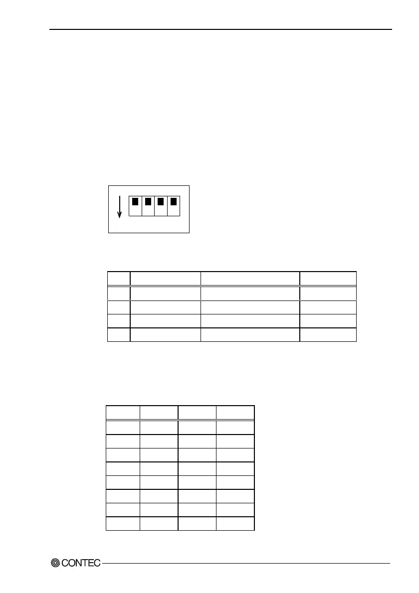
Dip Switch
A DIP switch is located on the left side of the unit.
Switches 1 - 3 are used as the ID setting when connecting multiple
touch panels via USB. See Chapter 9 for details on connecting
multiple touch panels via USB.
Notes!
- When connecting via RS-232C or a single USB connection, set
switches 1 - 3 to OFF. (The default factory setting)
- Ensure that the power is turned OFF before changing the DIP
switch settings.
ON
1234
Figure 3.9. Dip Switch
Table 3.4. Setting a Dip Switch
No. Setting Setting description Factory setting
1 USBID0 Setting the USB touch panel ID OFF
2 USBID1 Setting the USB touch panel ID OFF
3 USBID2 Setting the USB touch panel ID OFF
4 Reserved Reserve (Leave this at OFF.) OFF
The USB ID0, 1 and 2 settings specify the ID when connecting
multiple touch panels via USB.
Table 3.5. Setting a USB ID
USB ID USBID0 USBID1 USBID2
7OFFOFFOFF
6ONOFFOFF
5 OFF ON OFF
4ONONOFF
3OFFOFFON
2ONOFFON
1 OFF ON ON
0ONONON