Do you have a question about the Contrec 212 and is the answer not in the manual?
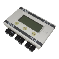
Explains how to designate model numbers for the device.
Lists various unit conversion factors used in the manual.
Details how to navigate and view data on the device's display.
Explains how to check programmed parameters without making changes.
Describes programmable metric and US units for display readings.
Defines the low frequency cutoff for flow signal registration to prevent errors.
Explains how to compensate for temperature sensor offsets for accuracy.
Details the four operational modes: Heating, Cooling, Heating/Cooling, Charge/Discharge.
Describes programming peak and off-peak times for energy recording.
Explains the facility to log energy totals at fixed intervals.
Details the Meter-bus hardware and protocol for data communication.
Describes the infra-red communication option, noted as not implemented.
Explains the RS485 interface using the Modbus RTU protocol.
Details how to connect various types of flowmeters for input signals.
Explains the connection procedure for RTD temperature sensors.
Describes the power supply requirements and connection options for the unit.
Details the pulse output connections and programming options.
Explains the alarm relay outputs and their programmable functions.
Describes the 4-20mA output option and its specifications.
Instructions for mounting the unit on a wall using provided brackets.
Details the procedure for panel mounting the unit and its rear view.
Step-by-step guide to safely remove the front panel for access.
Describes the verification seal used to prevent tampering with calibration.
Guidelines for proper wiring, shielding, and EMC compliance.
Lists and describes the function of each terminal on the unit.
| Brand | Contrec |
|---|---|
| Model | 212 |
| Category | Measuring Instruments |
| Language | English |