212-M-V2.1
48 Input & Output Connections
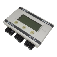
6. INPUT & OUTPUT
CONNECTIONS
6.1 FLOWMETER INPUT
The instrument will accept frequency or pulse inputs from a wide range
of flowmeters.
Examples of connection diagrams are shown on the following pages.
Note that it may be necessary to change the position of the links as shown.
These links are accessible by removing the front panel as detailed in section
7.2 and the link positions are shown in the drawing in section 7.3.
Link 1 Links in an input filter for a reed switch. The
maximum input frequency is approximately 500Hz
with this filter.
Link 2 Link for coils (eg. turbine or paddlewheel flow sensors).
Link 3 Not connected. This position is selected if links 1 or
2 are not required.
Link 6 Selects a two wire proximity switch when in position B.
Link 7 Selects a coil input when in position B.
The links are made via small black caps which fit over the two connecting
posts thereby creating the link.
The input on terminals 10 or 11 is limited to 30 volts maximum.
Note: After connecting the flowmeter, it is also necessary to program
the flowmeter factor. This is supplied by the flowmeter manufacturer
and represents the number of pulses per litre, m3, gallon or ft3 that
the flowmeter outputs for each unit of volume. It is often referred to
as the K-factor.