Safety
Information
Product
Information
Mechanical
Installation
Electrical
Installation
Keypad and
Display
Parameters
Quick Start
Commissioning
Diagnostics Options Parameter List
UL Listing
Information
Commander SK Size 2 to 6 Getting Started Guide 49
Issue Number: 2 www.controltechniques.com
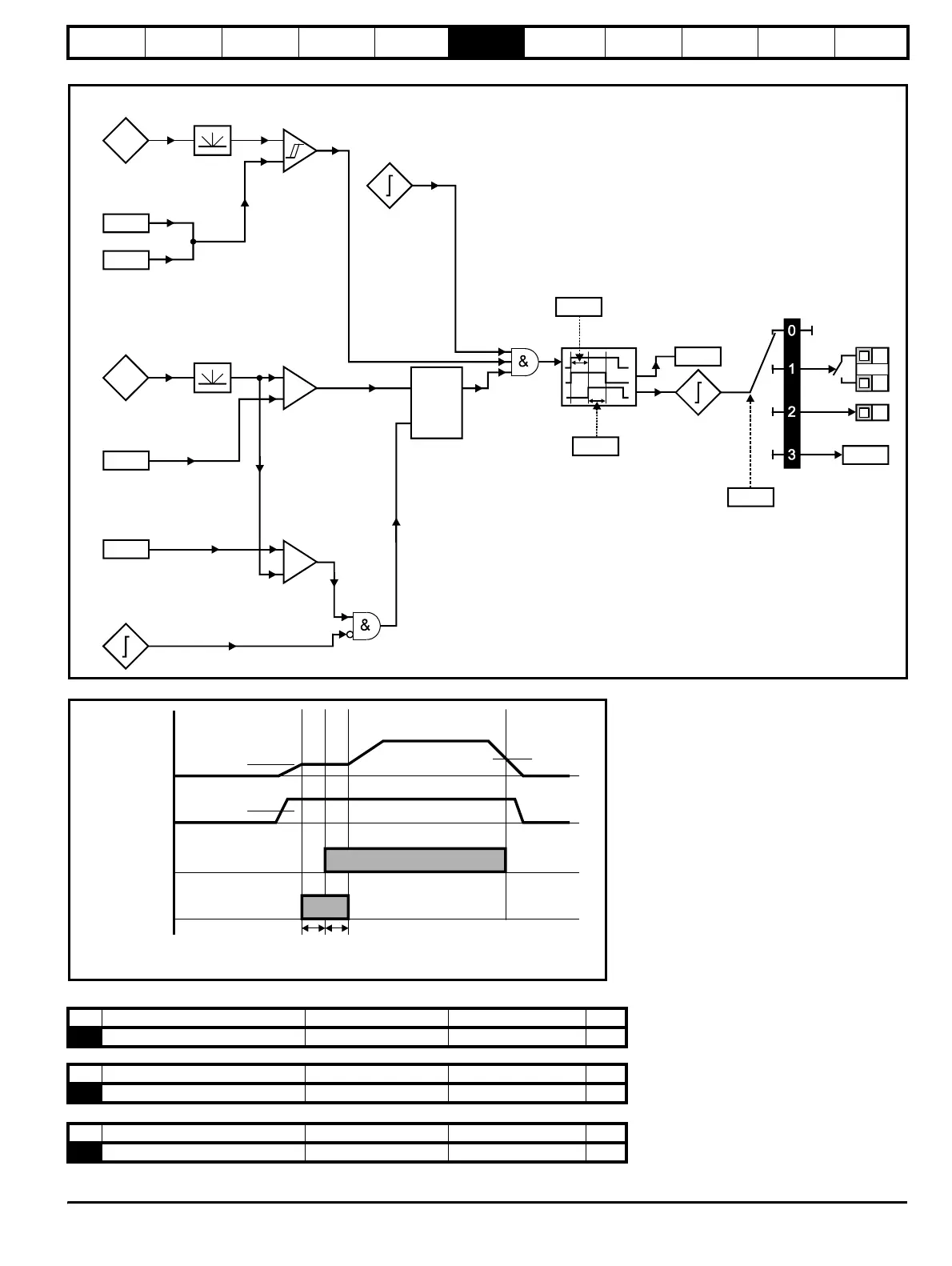
Figure 6-12 Brake function diagram
Figure 6-13 Brake sequence
Pr 52 to Pr 54 appear when a fieldbus Solutions Module is fitted to the drive
See the appropriate fieldbus Solutions Module manual for further information.
Current
magnitude
Brake release
current threshold
Brake apply
current threshold
46
47
+
_
Motor
frequency
Brake release
frequency
Brake apply
frequency
48
49
+
_
+
_
Reference
enabled
Latch
Drive
active
In
Out
Reset
Pre-brake
release
delay
50
Post brake
release
delay
51
Brake
release
Brake
controller
enable
12
T5
T6
B3
User
programmable
Brake
disabled
Ramp
hold
No Function Range Defaults Type
52 Fieldbus node address 0 to 255 0 RW
No Function Range Defaults Type
53 Fieldbus baud rate 0 to 8 0 RW
No Function Range Defaults Type
54 Fieldbus diagnostics -128 to +127 0 RW
Pr Brake
release frequency
48:
Pr : Brake release
current threshold
46
Ramp hold
Pr :
Brake appl
frequency
49
Pr :
Pre brake
release dela
50
Pr :
Post brake
release dela
51
Brake release
Output current
Output frequency