Safety
Information
Product
Information
Mechanical
Installation
Electrical
Installation
Keypad and
Display
Parameters
Quick Start
Commissioning
Diagnostics Options Parameter List
UL Listing
Information
Commander SK Size 2 to 6 Getting Started Guide 55
Issue Number: 2 www.controltechniques.com
Table 8-2 Alarm warnings/Display indications
If no action is taken when an alarm warning appears, the drive will trip on the appropriate fault code.
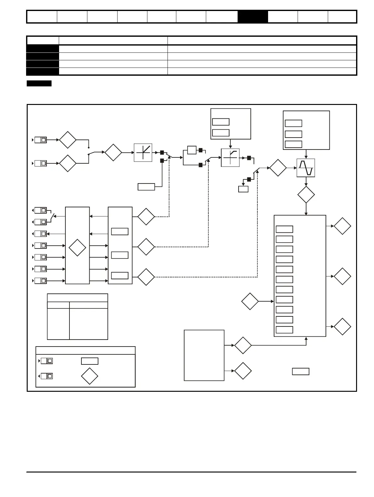
Figure 8-1 Diagnostics logic diagram
Cooling fan control
The cooling fan on a Commander SK size 2 is a dual speed fan and on
sizes 3 to 6, it is a variable speed fan. The drive controls the speed at
which the fan runs based on the temperature of the drives heatsink and
also the drive’s thermal model system. The cooling fan on Commander
SK size 6 is a variable speed fan which requires an external +24Vdc
power supply.
See section 4.2 Heatsink fan on page 31.
Display Condition Solution
OVL.d I x t overload Reduce motor current (Load)
hot Heatsink/IGBT temperature high Reduce ambient temperature or reduce motor current
br.rS Braking resistor overload See Commander SK Advanced User Guide
AC.Lt Drive is in current limit See Commander SK Advanced User Guide
NOTE
Analogue inputs
94
95
81
Analogue input 1 (%)
Analogue input 2 (%)
Digital I/O
XX
Digital I/O
Read
word
Pr
90
Sequencer
92
93
91
Jog
selected
Reverse
selected
Reference
enabled
X-1
1
0
0
1
0
1
0Hz
82
Pre-ramp
reference (Hz)
84
DC bus
voltage
42
41
40
39
38
37
32
09
08
07
06
Motor rated
current
Motor rated
speed
Motor rated
voltage
Motor power
factor
Dynamic V to f
select
Switching
frequency
Autotune
Motor rated
frequency
No. of motor
poles
Voltage
mode select
Voltage
boost
Motor control
03
Acceleration
rate
Deceleration
rate
Ramps
02
01
Minimum
speed
Maximum
speed
Speed clamps
83
Post-ramp
reference
(Hz)
85
Motor
frequency
86
Motor
voltage
87
Motor
speed
rpm
88
89
Motor active
current
Motor current
Current
measurement
15
Jog
reference
Digital I/O read word Pr
90
Terminal Binary value for XX
B3 1
B4 2
B5 4
B6 8
B7 16
T6/T5 64
Frequency
reference
selected (Hz)
04
T2
T4
T6
T5
B3
B4
B5
B6
B7
XX
XX
Key
Read-write (RW)
parameter
Read-only (RO)
parameter
Input
terminals
Output
terminals
B3
B4
11
12
Start/stop
logic select
Brake
controller
enabled
31
Stop mode
select
Ramp mode
select
30
10
Parameter
access