Page 48
Initial Start-Up con’t
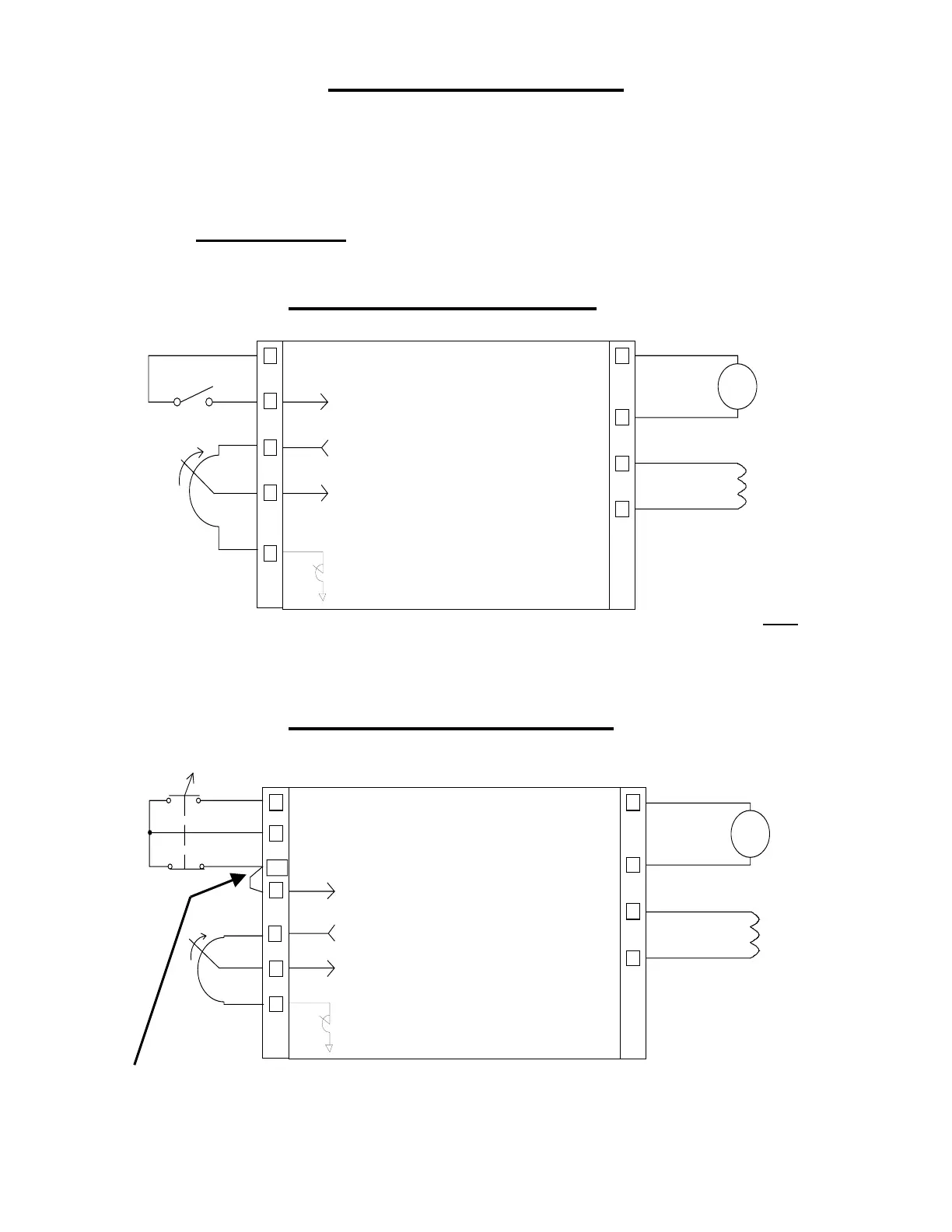
A minimal number of connections are made to the terminal strip (see diagrams
below). If the drive is an enclosed unit with operator devices (start/stop and speed pot)
only the jumper from terminal block TB2-5 to TB2-5A needs to be made- this is a
temporary connection only intended for System Interlock - see Application Safety
a) Regulation Mode: In this procedure, leave jumper in speed regulation
(JP2 = SPD).
For Chassis Units Only
3
5
6
7
8
close to run
Speed Ref
Drive run enable
A+
A-
F+
A1
A2
F1
F2
Motor
Armature
Motor Fiel
FOCUS 1
Chassis Unit
+10VDC
Min Speed
F-
Note:
Permanent
Magnet Motors
do not have
Field F1 & F2,
connections
For Enclosed Units Only
3
5
6
7
8
Speed Ref
Drive run enable
A+
A-
F+
A1
A2
F1
F2
Motor
Armature
Motor Fiel
FOCUS 1
Chassis Unit
+10VDC
Min Speed
F-
5A
4
Speed
Potentiometer
Start / Stop
Switch
And
Speed
Potentiometer
Located on
front cover
Drive will not start without
this. This is intended for
system interlock- see
Application Safety