EasyManua.ls Logo

Control Techniques Emerson Focus 1

Control Techniques Emerson Focus 1
66 pages
To Next Page IconTo Next Page
Loading...
Page i
User Guide
P/N: FOCUS1-UG
Revision: A1
Date: Feb 10, 2005
© Control Techniques Drives, Inc. 2005
Focus 1
¼ to 2HP Single Phase,
Uni-Directional
Non-Regenerative
DC Drive

Questions and Answers:

Control Techniques Emerson Focus 1 Specifications

General IconGeneral
HorsepowerUp to 5 HP
Power RatingUp to 3.7 kW
Field SupplyFixed or variable, up to 5A
Regulation±1%
ProtectionOvercurrent, overvoltage, undervoltage, overtemperature, field loss
CommunicationRS485

Summary

Focus 1 DC Drive Overview

General Information and Disclaimers

Customer Support Channels

Safety Definitions and Symbols

Warning Symbol Meaning

Indicates a potentially hazardous situation that could result in death or serious injury if not avoided.

Caution Symbol Meaning

Indicates a potentially hazardous situation that could result in minor or moderate injury if not avoided.

Caution Symbol (Property Damage)

Indicates a potentially hazardous situation that could result in property damage if not avoided.

Safety Considerations and Precautions

General Safety Precautions

Highlights hazards from high voltages, currents, and mechanical equipment, requiring trained personnel.

Enclosure Requirements

Specifies enclosure needs for preventing access and contamination ingress, suitable for pollution degree 2.

Setup, Commissioning, and Maintenance Safety

Emphasizes careful consideration of drive settings and parameter changes for safe operation.

Machinery Safety Compliance

Discusses compliance with EU directives for machinery safety and implications for control functions.

General Safety Warnings and Practices

AC Supply Isolation Device

Explains the necessity of an isolation device or disconnect before servicing the drive.

Grounding (Earthing, Equipotential Bonding)

Stresses proper grounding via conductor sufficient to carry fault current.

Fusing and Control Circuit Isolation

Covers requirements for input fusing and ensuring control circuits are isolated from human contact.

Introduction to Focus 1 Drive Models

Chassis Model Description

Details the chassis model intended for mounting within a user-supplied cabinet.

Enclosed Model Description

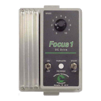
Describes the NEMA 1 enclosed version with integrated controls for convenient operation.

Motor Compatibility Guide

Shunt Wound Motor Connections

Details the typical 4-wire connections for shunt wound motors (Armature and Field leads).

Motor Armature Voltage and Field Requirements

Guides selection based on motor armature voltage (90/180Vdc) and field resistance.

Permanent Magnet Motor Compatibility

Speed Control Mechanisms and Stopping

Armature Voltage Feedback for Speed

Explains speed regulation using armature voltage feedback for up to 1% accuracy.

Quick Stop Functionality with Dynamic Braking

Describes how dynamic braking provides quick stopping action and motor turning resistance.

Power Outage Behavior

Details motor behavior during power outages for Shunt Wound and Permanent Magnet motors.

Receiving, Inspection, and Storing Procedures

Receiving and Inspection Procedures

Guides users on checking shipment for damage and verifying contents against purchase order.

Storage Instructions for Warranty

Outlines conditions for storing the drive (clean, dry, temperature range) to maintain warranty.

Performance Features of the Focus 1 Drive

Solid State Power Bridge and Fusing

Highlights the reliable power bridge and AC line fusing for maximum protection.

Current Limit and Speed Regulation

Details selectable current limit ranges and 1% speed regulation accuracy.

Indicator and Certification Features

Mentions the circuit board LED indicator and UL/cUL listing for compliance.

Nameplate Information and Identification

Enclosed Unit Nameplate Details

Shows nameplate details including Part #, Serial #, input/output ratings for the enclosed model.

Chassis Unit Nameplate Details

Shows nameplate details including Part #, Serial #, input/output ratings for the chassis model.

Drive Specifications and Ratings

Catalog Number and Enclosure Ratings

Lists catalog numbers, enclosure types (Chassis, NEMA 1), and HP ratings.

AC Input and DC Output Parameters

Details voltage and current ratings for AC input (120/240Vac) and DC output (Armature/Field).

Detailed Performance and Operating Specifications

Performance Specifications

Includes service factor, speed regulation, armature voltage, speed range, and efficiency.

Drive Operating Conditions

Specifies altitude (3300ft) and ambient temperature limits for chassis and enclosed models.

Internal Adjustments and Customer Selections

Explains potentiometer functions (Max Speed, Min Speed, IR Comp) and jumper selections.

Operator Functions and Control Specifications

Operator Functions for Chassis and Enclosed Models

Compares operator functions (Speed Adjustment, Start/Stop, Fwd/Rev) available on different models.

Control Circuit Specifications

Lists logic control power (24Vdc), speed potentiometer (5000 ohm), and input signal requirements.

Focus 1 Optional Kits

Lists available option kits including M-Contactor, Dynamic Braking, and interface options.

Focus 1 Chassis Dimensions

Chassis Mounting Suitability

Advises on mounting the chassis model in user enclosures, considering temperature limits.

Focus 1 Enclosed Dimensions

NEMA 1 Enclosure Suitability

Describes suitable environments for the NEMA 1 enclosure, avoiding steam, oil, or chemical fumes.

Focus 1 Option Kits - Contactor and Braking

Focus 1 Contactor and Reversing Kits

Explains kits providing motor disconnection and dynamic braking poles for safety and code compliance.

Focus 1 Dynamic Braking Kits

Details specific part numbers for dynamic braking resistors sized for rapid motor stopping.

Focus 1 Option Kits - NEMA 412 and Signal Isolator

NEMA 412 Kit for Wash Down Environments

Details the kit for converting the standard NEMA 1 enclosure to a NEMA 4/12 rating.

Signal Isolator Board Functionality

Explains the board for isolating control signals from potential ground differences.

Focus Family Operator Station and Meter Options

Remote Operator Station Models

Describes the two models of remote operator stations with speed pot and start/stop buttons.

Remote Percent Meters and Calibration

Details meters for displaying motor speed and associated calibration boards.

Ten-Turn Precision Speed Potentiometer

Introduces a multi-turn speed potentiometer for precise and repeatable speed setting.

Focus Series Interface Options

120 Vac Interface for StartStop and Jog

Details kits providing 120VAC interface for three-wire Start/Stop and Jog functions.

120 Vac Interface for System ReadyTrip

Describes kits for system ready and external trip functions via 120VAC interface.

Customer Connections and Start-Up Guidelines

Start-Up Procedure Steps

Lists sequential steps from Receiving & Inspection to Start-up of Drive.

Critical Start-Up Safety Warnings

Emphasizes warnings regarding electrical shock, improper installation, and hazardous voltages.

Incoming Power and Grounding Requirements

Incoming Power Requirements

Specifies fused AC line disconnects and single-phase AC voltage requirements per NEC.

Grounding the Control System

Instructs on connecting to earth ground via mounting screws or lugs for safety.

Wiring Guidelines for DC Drives

Provides wiring charts, notes on wire types, gauge, and prohibited connections.

Motor Wiring and Option Kit Installation

Motor Rotation Correction

Explains how to correct wrong motor rotation by exchanging armature or field leads.

Option Kit Installation Precautions

Advises against installing option kits before verifying basic drive operation to simplify troubleshooting.

Drive Power Wiring Diagram

AC Line Input and Earth Connection

Illustrates connections for AC power input (L1, L2) and earth ground.

Motor Armature and Field Lead Connections

Identifies connections (A+, A-, F+, F-) for motor armature and shunt field leads.

Control Wiring Terminal Connections

Terminal Block (TB2) Descriptions

Explains the function of each pin from 1 to 8 for drive control inputs and outputs.

Control Circuitry Isolation Warning

Warns against grounding control circuitry, as it can cause immediate failure and void warranty.

Terminal Strip Connections - Enclosed Model

Standard StartStop and Speed Potentiometer Wiring

Illustrates wiring for the integrated Start/Stop switch and Speed Potentiometer on the enclosed unit.

System Interlock Connection Requirement

Highlights a critical connection (TB2-5 to 5A) required for system interlock and preventing start-up.

Chassis Model Control Connections

Chassis Model Wiring Overview

Shows connections to the drive control terminal strip, including the Speed Potentiometer.

System Interlock for Chassis Model

Points out the connection required for system interlock, preventing start-up without it.

Speed Potentiometer Wiring Configuration

Unipolar Speed Potentiometer Wiring Diagram

Illustrates connections for +10Vdc supply, Speed Command (wiper), and Common/Min Speed terminals.

Shield Connection Warning

Warns against connecting the speed pot shield to Earth to prevent permanent damage.

Customer Jumper Selections - Programming

Jumper Programming Safety Warning

Warns against attempting jumper programming while the control is operational; requires power lockout.

J1: Speed or Current Control Mode

Details the function of Jumper 1 for selecting between Speed (SPD) or Current (CUR) control mode.

J3: Armature Voltage Level Selector

Explains the function of Jumper 3 for selecting between Low (90 Vdc) or High (180 Vdc) armature voltage.

Input Voltage Selection via Jumpers

Jumper Positions for 120240 Vac Input

Shows jumper settings (A to E/B to D for 120Vac, A to C/B to C for 240Vac) for input voltage.

Voltage Selection Caution

Warns that applying 240Vac to a 115Vac configured unit will damage the drive.

Current Feedback Range (J2) Configuration

J2 Settings for 115 vac90 vdc Motors

Lists J2 jumper positions (Lo, Med, Hi) based on motor HP and DC output current for 115Vac input.

J2 Settings for 230 vac180 vdc Motors

Lists J2 jumper positions (Lo, Med, Hi) based on motor HP and DC output current for 230Vac input.

Current Control Mode Operation

Jumper Settings for Torque Regulator

Details jumper settings (J1 to CURR, J2 range, J3 to CURR REG) for torque regulation.

Torque Mode Overspeed Protection Warning

Warns about potential overspeed in torque mode and the necessity of external overspeed protection.

LED Status Indicators

Run LED Functionality

Explains that the red LED illuminates when the run relay is energized, indicating active operation.

Basic Customer Adjustments - Potentiometers

Maximum Speed (MAX SPD) Adjustment

Details how to set the maximum motor speed using the MAX SPD potentiometer.

Minimum Speed (MIN SPD) Adjustment

Explains how to set the minimum motor speed using the MIN SPD potentiometer.

Potentiometer Adjustments for Motor Speed

MAX SPD Potentiometer Adjustment Guide

Shows the location and provides guidance for adjusting the MAX SPD potentiometer.

MIN SPD Potentiometer Adjustment Guide

Shows the location and provides guidance for adjusting the MIN SPD potentiometer.

Additional Tuning Adjustments - IR Compensation

IR COMP Potentiometer Adjustment

Guides adjustment of the IR COMP pot to recover speed lost due to load or prevent hunting.

Start-up Guide Worksheet and Mode Selection

Start-up Information Recording

Lists required drive model, serial, motor nameplate data (voltage, current, RPM).

Regulation Mode Selection: Speed vs. Torque

Recommends initial setup in Speed Regulation mode before switching to Torque mode.

Focus 1 Jumper Setup Worksheet

Jumper Setup Step 3: Field Voltage and Input Power

Details jumper settings for 100Vdc field voltage and 120Vac input power.

Jumper Setup Step 4: Field Voltage and Input Power

Details jumper settings for 200Vdc field voltage and 230Vac input power.

Jumper Setup Steps 5 & 6: Armature Voltage and Input Power

Guides jumper settings based on armature voltage (110Vdc) and input voltage (120Vac).

Armature Current Programming (J2) Configuration

J2 Jumper Settings for Current Feedback Range

Correlates catalog number, DC output current, and J2 position for armature current feedback.

Application Safety Considerations

Installers Responsibility for Safety

Stresses the installer's role in ensuring operator safety through system design and testing.

Contactor Option for Power Line Disturbance

Recommends contactor kits to prevent unintended motor movement during power line disturbances.

System Interface Suggestions for Safety

System Enable Logic

Suggests using a permissive or System Enable to ensure safe operation based on machine conditions.

Relay Logic System for Focus Drive

Outlines external relay logic for an overall System Enable, integrating safety interlocks.

Contactor Option for Motor Disconnection

Explains how contactor kits disconnect the motor from the drive power section when remote start opens.

Initial Start-Up Procedure

Initial Start-Up without Option Kits

Describes verifying basic speed regulator operation in an out-of-box state with no option kits installed.

Option Kit Installation Timing

Advises against installing option kits before verifying basic operation to simplify troubleshooting.

Initial Start-Up Connections and Modes

Chassis Unit Start-Up Connections

Shows minimal connections for chassis units during start-up, including speed potentiometer.

Enclosed Unit Start-Up Connections

Shows minimal connections for enclosed units, including Start/Stop switch and Speed Pot.

Regulation Mode Selection (JP2=SPD)

Instructs to leave JP2 in speed regulation (SPD) for initial start-up procedure.

Start-Up and Current Regulator Setup

Applying Power and Basic Motor Test

Details steps for starting the drive, verifying motor rotation, and acceleration.

Basic Setup for Current (Torque) Regulator

Explains jumper settings (JP1, JP3 to CURR) and input for current/torque regulator mode.

Troubleshooting Guide - Important Safeguards

General Troubleshooting Safeguards

Emphasizes disconnecting power and reading diagrams before any maintenance or troubleshooting.

Motor Inspection and Maintenance Checks

Details regular checks for motor cleanliness, cooling passages, impeller, brushes, and bearings.

Troubleshooting Overview and Techniques

Suggested Troubleshooting Training

Recommends studying manuals, gaining experience, and training in test instrument use.

Maintenance Records and General Troubleshooting

Stresses record-keeping and lists common drive failure causes like loose connections or grounding.

Notes for Troubleshooting Technicians

Provides guidance on using multimeters, oscilloscopes, reading schematics, and checking fuses.

Oscilloscope Safety for DC Drives

Oscilloscope Connection Hazards

Warns about connecting oscilloscope ground to a 'hot' chassis type drive, which can cause severe shock.

Eliminating Ground Connection for Measurement

Details methods to eliminate the oscilloscope's ground connection for safe measurement of control signals.

Typical Line Power Oscilloscope Setup

Line Power Oscilloscope Ground Pin

Highlights that the earth ground pin on a typical oscilloscope is tied to the probe's ground clip.

Portable and AC Line Powered Oscilloscope Methods

Portable Battery Powered Oscilloscope Use

Recommends battery-powered scopes without adapters as the best method for observing drive waveforms.

Differential Channel Method for AC Line Scopes

Explains the differential channel method using two probes to avoid ground clips and ensure safety.

Oscilloscope Grounding Solutions

Isolation Transformer Method

Describes using a small isolation transformer to power the scope, eliminating earth ground connection.

Least Preferred Method: Ground Pin Modification

Discusses cutting off the ground pin or using a 'cheater' adapter, noting potential warranty voiding.

Basic Troubleshooting Symptoms and Causes

Troubleshooting: Control Appears Dead

Covers causes like missing jumpers, no AC power, loose connections, or defective components.

Troubleshooting: Line Fuses Blow

Addresses causes for blown fuses or tripped breakers: incorrect voltage, shorts, or wiring errors.

Troubleshooting: Fuses Blow When Speed Pot Advanced

Identifies issues like motor overload, defective components, or worn motor brushes.

Troubleshooting: Motor Does Not Reach Full Speed

Lists causes such as overload, low MAX SPD setting, low AC voltage, or incorrect jumper programming.

Troubleshooting: Motor Operation Issues

Motor Runs in Wrong Direction

Explains how to correct motor direction by exchanging armature or field leads.

Motor Does Not Maintain Speed Under Load

Covers causes like low IRCOMP, motor overload, or incorrect jumper programming.

Motor Does Not Come to Full Stop

Lists potential causes for the motor failing to stop, such as incorrect potentiometer settings.

No Speed Control Issues

Addresses issues related to defective components, incorrect wiring, or potentiometer problems.

Basic Test Setup - Light Bulb Test

Basic Test Power Wiring Diagram

Illustrates wiring for connecting a 75W light bulb to the armature output for testing.

Drive Set-up and Circuitry Checkout

Record Drive Set-up Before Test

Instructs to record jumper settings before performing the light bulb test for later restoration.

Basic Armature Circuitry Checkout

Explains checking armature circuitry with a light bulb and voltage measurement (approx. 90Vdc).

Field Supply Checkout Procedure

Details checking the field supply using a light bulb (75W or less) across F+/F- terminals.

Application Notes and Resources

Application Notes for Focus Products

Provides a list of available application notes, technical notes, and replacement instructions on the website.

Achieving Isolation in Non-Regenerative Drives

Control Terminal Connection Hazards

Warns against connecting control terminals to earth ground due to the risk of shorting circuit board traces.

Solutions for Earth Grounded Control Inputs

Focus 3 Signal Isolator Board (F3 NSBD)

Describes the signal isolator board as Solution #1 for isolating control signals and preventing ground loops.

Solutions Requiring Isolation - Isolation Transformer

Isolation Transformer KVA Calculation

Provides a formula (KVA = 1.5 x Rated Armature Current x Voltage) for calculating transformer size.

Critical Components and Replacement Parts

Main Control Board and Replacement Instructions

Identifies the main control board and provides website link for replacement instructions (CTRI219).

Speed Adjust Pot and Switches

Lists part numbers for the Speed Adjust Potentiometer and operator switches (Start/Stop, Fwd/Rev).

Power Block and Fuses

Lists part numbers for the Power Block (3720-004) and Fuses (3705-032, 15A).

Related product manuals