Page 59
Record Drive Set-up BEFORE performing Light bulb test
Basic Armature Circuitry Checkout
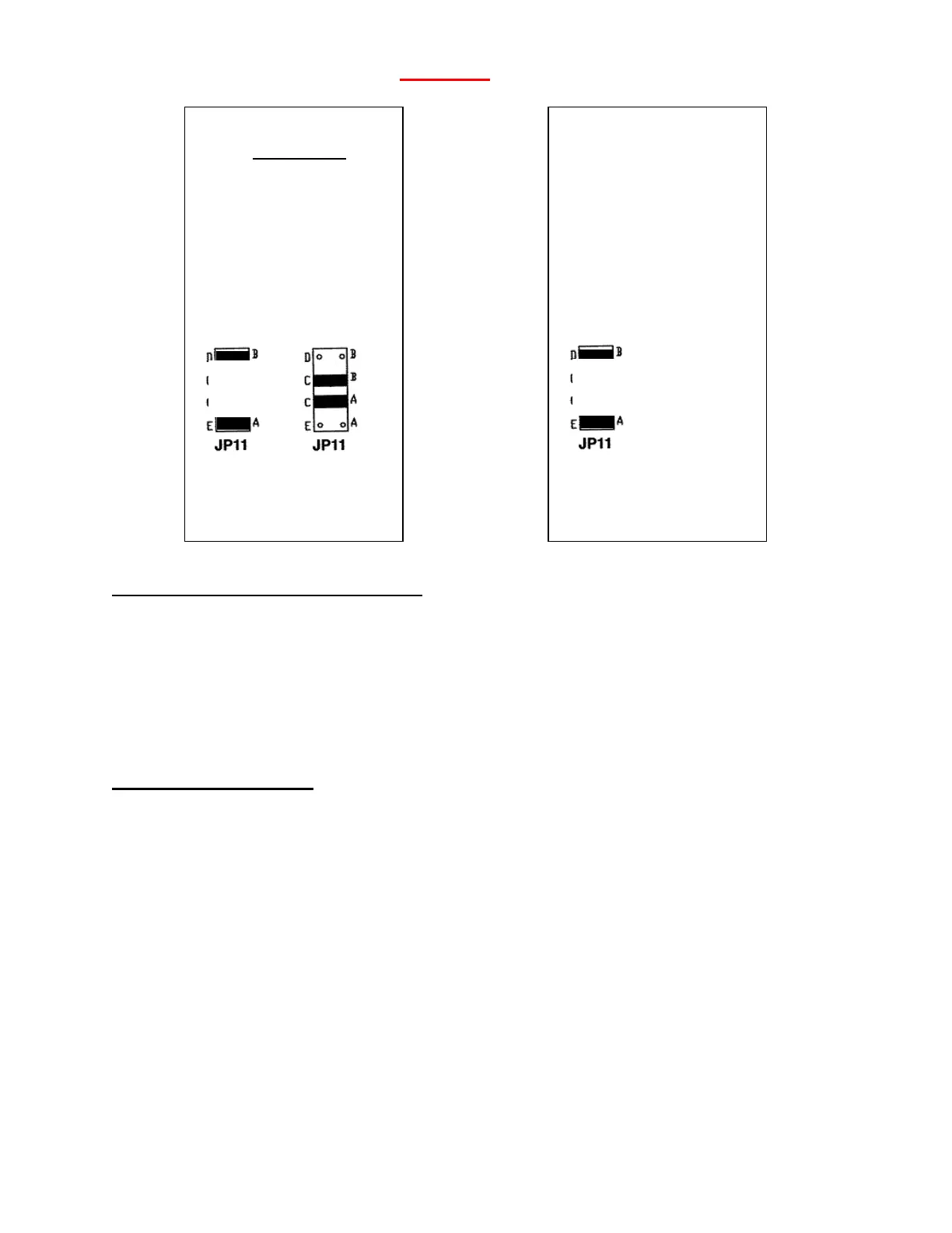
After the Focus is wired as shown on the previous page and the jumper set as indicated
above, 115 Vac power could be applied and the Focus should cause the light bulb to
vary in brightness from nothing to full brightness. One could measure the voltage
across the bulb and it should be about 90 Vdc at maximum brightness. This would
verify the basic Start/Stop, Speed command, Power Supply, Regulator and Power
Sections.
Field Supply Checkout
If one wants to check the Field Supply, power should be removed and the light bulb
moved over to the F+ and F- terminals (use a 75 W bulb or less for the field. Use of
greater than 75 W could permanently damage the Field rectifiers). Then upon
application of power, the light bulb should light to full brightness and the voltage across
the light bulb should measure about 100 Vdc.
If the Focus passes these basic tests, the drive should be OK and the drive
should be able to run a good motor at least in Armature Voltage feedback (JP4 in ARM).
Reset jumpers back to the “Before Test Recorded Settings” except for JP4 and re-
check.
If the motor has a shunt field, it should measure at least:
200 ohms if Nameplate indicates 200 Vdc Field
100 ohms if Nameplate indicates 100 Vdc Field
Before Test
Circle One
JP1 SPD CUR
JP3 ARM TACH
JP2 Hi Med Low
A B C D
: :
115 Vac 230 Vac
Operation
Test
JP1 SPD
JP3 ARM
JP2 Low
: :
115 Vac Operation