Page 29
Control Wiring
TERMINAL CONNECTIONS (TB2) & DESCRIPTIONS
Pin Number
1 Forward: Connected to “quick connect” 1 as a tie point for the Motor
Reversing Contactor Kit forward / reverse switch, or the motor contactor
Kit
2 Reverse: Connected to “quick connect” 1 as a tie point for the Motor
Reversing Contactor Kit forward / reverse switch.
3 +24 Vdc Supply: Powers the logic inputs to the drive. It is not intended
for it to be used to power external circuits. External use will void
warranty.
4 Run Relay Contact: Relay common connection for seal-in circuit.
5 Run Relay: When +24 Vdc is applied to this terminal, the Run relay picks
up, the Speed loop and the Current loop are enabled, and the clamp on
the SCR firing circuits is released.
5A Motor Thermal tie-point: No connection internal
see Application Safety
6 +10 Vdc Speed pot supply voltage: Maximum load is 5ma
7 Standard Speed command input: Typically this input is connected to
the wiper of the speed pot wiper. Input impedance: 40Kohm.
8 Minimum Speed connection: This sets a minimum motor speed when
the speed potentiometer is used (does not set a minimum speed when an
isolated 0 to 10vdc speed reference is used).
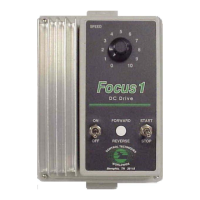
The Focus 1 drive control circuitry is not isolated *. No points in the control
circuitry, including common, should be connected to earth ground unless
specifically shown on the supplied wiring diagrams. No grounding connections
should be made on the terminal block. Improper connections to ground,
including speed potentiometer connections, will result in immediate control
failure and will void the factory warranty.
* See How to Achieve Isolation on page 60 of this manual

 Loading...


