16 FXM5 User Guide
www.controltechniques.com Issue Number: 5
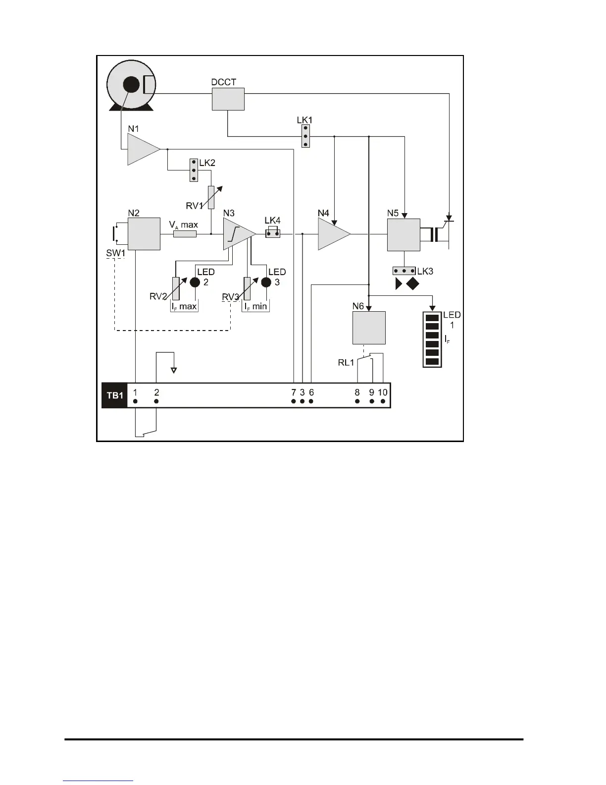
4.2 Control-circuit description
Figure 4-2 Main elements of the control circuit
Refer to Figure 4-2. The control circuit comprises four main elements, as follows:
• Armature-voltage monitor (N1, N2)
• Field-current limiter (N3)
• Field-current amplifier (N4)
• Thyristor-bridge driver (N5)
The elements that are used depend on the system control mode that is in operation.
4.2.1 Main elements
The armature-voltage is applied to amplifier N1. The output is compared with a voltage
reference N2. Preset potentiometer RV1 (MAX ARM V) and jumper LK2 are used to
adjust the threshold level. When a Mentor II Drive is used parameter 6.07 sets the
threshold. When the threshold level is not reached, the resulting signal causes the field-
current limiter (N4) and thyristor-bridge driver (N5) to apply full voltage to the field
winding of the motor. When the threshold is reached, the field-current limiter (N4) and
thyristor-bridgedriver(N5)causethefield-windingvoltagetobereduced.
A direct-current current-transducer (DCCT) in the field-winding circuit monitors the field
current. The output of the DCCT is applied to a negative feedback loop so that, by
varying the field-winding voltage, the FXM5 controller is in control of the field current.
The setting of jumper LK1 and the number of primary-winding turns through the DCCT
define the absolute maximum current (I
F
max) that can be produced by the controller