FXM5 User Guide 17
Issue Number: 5 www.controltechniques.com
(see section 4.5 Changing the DCCT primary winding turns on page 21). This value
shouldbesetatthenearestvalueabovetherequiredmaximumfieldcurrent.
Preset potentiometer RV2 (SET MAX FIELD) is used to set the required maximum field
current as a proportion of I
F
max. This current level occurs when the armature voltage is
below the preset threshold. LED2 indicates when the field current is at the maximum
level set using RV2. When a Mentor II Drive is used, the required maximum current can
be set using parameter 6.08.
Preset potentiometer RV3 (SET MIN FIELD) and switch SW1 are used to adjust the
minimum level of field current as a proportion of the current set using RV2. When SW1
is pressed, the LED bar indicator indicates proportion of the maximum current set using
RV2. The minimum level should be set for maximum required motor speed. When a
Mentor II Drive is used, the required minimum current can be set using parameter 6.10.
LED3 indicates when the field current is at or below the minimum level set using RV3.
The field-current feedback signal is monitored by an LED bar indicator, (LED1) and N6.
The LED bar indicates proportion of absolute maximum current (I
F
max) in steps of 0.1
(10%).
When the FXM5 controller is operating normally, field-failure relay RL1 is energized by
N6. When the field current is detected by N6 to be below the setting of RV2 (or the
minimum current set by a Mentor II Drive), the relay is de-energized. The contacts can
be used to break the AC supply to the armature.
4.3 Setting the thyristor control mode
All system control modes
4.3.1 Description
The thyristors are arranged as a full-wave bridge rectifier. The thyristors can be
controlled so that the bridge gives half-control or full-control. In both cases, full-wave
rectification is obtained. The results are as follows:
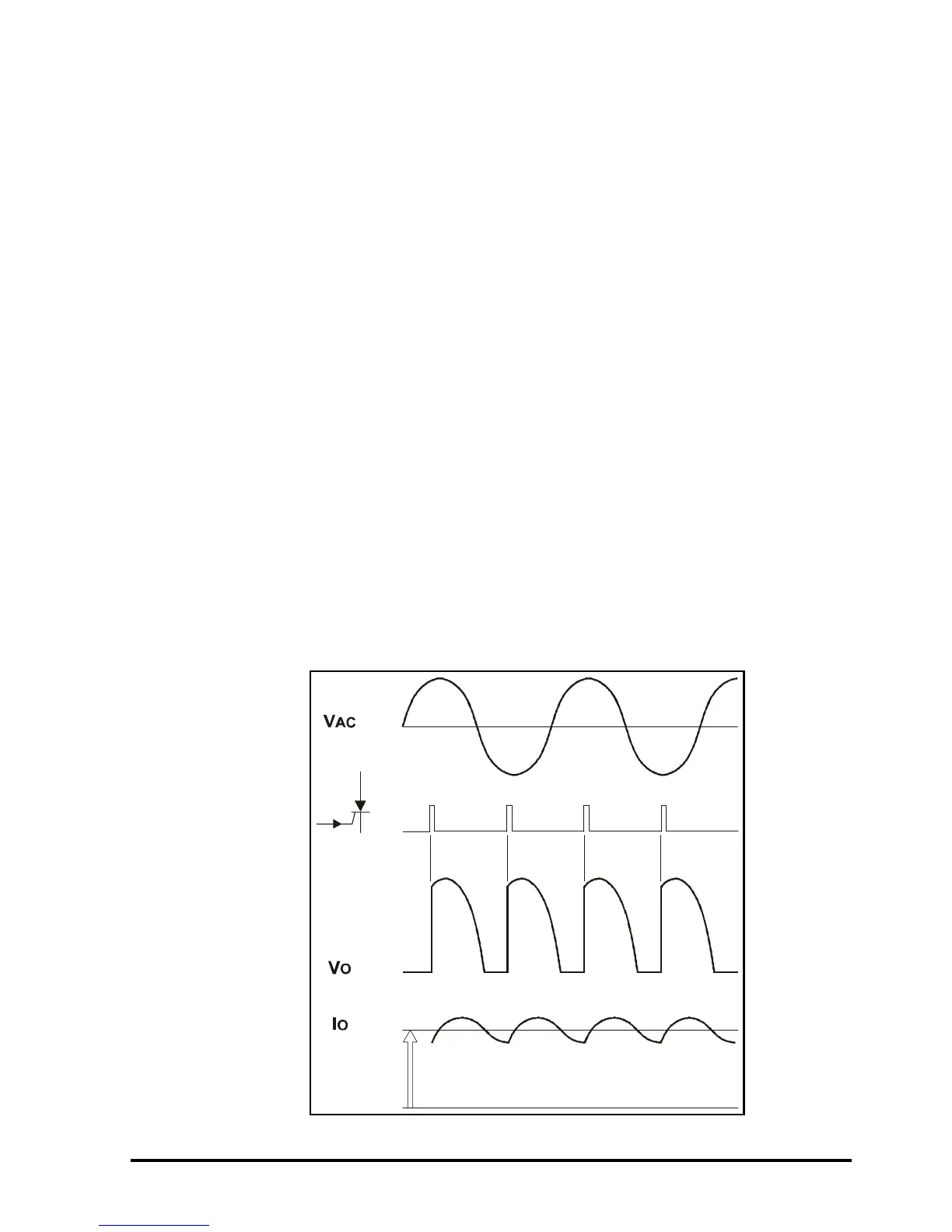
Half-control
Figure 4-3 Waveforms resulting from half-control