FXM5 User Guide 21
Issue Number: 5 www.controltechniques.com
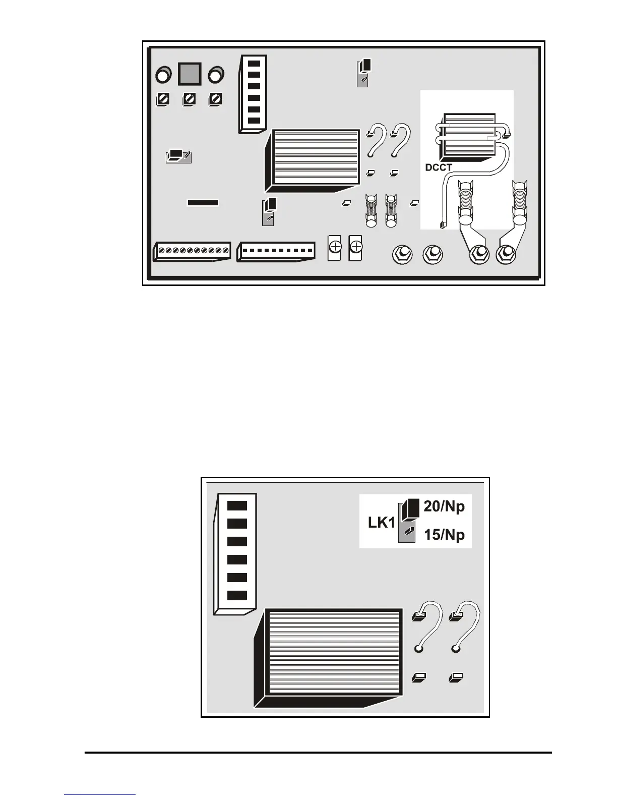
Figure 4-6 Location of the DCCT and wire loop
4.5 Changing the DCCT primary winding turns
Use the following procedure to change the number of turns:
1. Disconnect the loop of wire from the spade connectors on the printed-circuit board
and remove the wire from the DCCT.
2. Use insulated wire of sufficient length for the required number of turns and ensure
the wire is of the correct size for the maximum field current. (Refer to Cables and
fuses on page 5)
3. Loop the wire through the DCCT in the same direction as the original wire.
4. Fit a 6.25mm (0.276in) spade receptacle to each end of the wire.
5. Connect the wire to the spade connectors on the board.
6. Set jumper LK1 at the setting given in the table.
Figure 4-7 Location of jumper LK1