Safety
Information
Product
Information
Mechanical
Installation
Electrical
Installation
Getting
Started
Menu 0
Running
the motor
Optimisation
Macros
Advanced
Parameters
Technical
Data
Diagnostics
UL Listing
Information
104 Unidrive User Guide
www.controltechniques.com Issue Number: 9
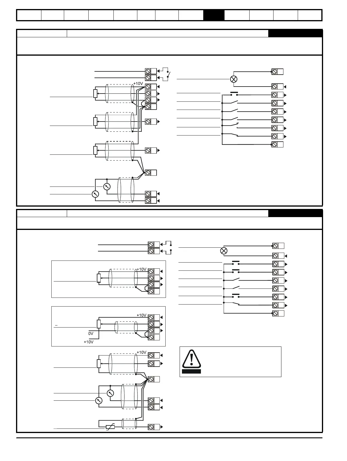
Macro 5 PID (set-point control)
2005
The PID control macro enables the drive's own internal PID controller to control the speed of the motor. Analog input 1 is configured for the main
speed reference, analog input 2 is the PID reference and analog input 3 is the PID feedback. A digital input selects between an analog speed
reference and the PID control.
Macro 6 Axis-limit control
2006
The Axis limit control macro configures the drive for use with limit switches so that the drive is stopped when a position limit has been reached. The
speed reference can be either unipolar or bipolar.
Status relay
Drive healthy
Frequency/speed
reference 1 (0 ~ 10V)
PID feedback
TORQUE
0V common
PID reference
(0 ~ 10V)
OL> AT SPEED
CL> AT ZERO SPEED
RESET
RUN FORWARD
RUN REVERSE
PID ENABLE
OL> External trip
CL> Drive enable
0V common
0V common
PID CONTROL
FREQ./SPEED CONTROL
0V common
SPEED
Signal
connector
1
2
4
5
6
3
7
11
9
10
8
23
24
25
27
28
29
30
31
JOG SELECT
26
Analog
frequency/speed
reference
10V
SPEED
TORQUE
0V common
OL> AT SPEED
CL> AT ZERO SPEED
RESET
LIMIT FORWARD
RUN FORWARD
OL> External trip
CL> Drive enable
0V common
Status relay
Drive healthy
RUN REVERSE
LIMIT REVERSE
Motor thermistor
Signal
connector
0V common
Analog
frequency/speed
reference 2
(local) 0 ~ 10V
Analog
frequency/speed
reference 1
(remote) 0 ~ 10V
0V common
Bipolar
Unipolar
+
1
2
4
5
6
3
7
11
9
10
8
4
5
6
3
4
23
24
25
26
27
28
29
30
31
Position the limit switches to allow for
the distance that will be travelled
during deceleration. This distance will
be increased if the deceleration time
is extended
WARNING
 Loading...

