Safety
Information
Product
Information
Mechanical
Installation
Electrical
Installation
Getting
Started
Menu 0
Running
the motor
Optimisation Macros
Advanced
Parameters
Technical
Data
Diagnostics
UL Listing
Information
78 Unidrive User Guide
www.controltechniques.com Issue Number: 9
Note
For the drive to operate correctly during and after synchronisation, Pr
0.07 Voltage mode selector must be set at Fd.
The drive starts a sequence of operations at one quarter of the rated
motor voltage in order to detect the frequency associated with the speed
of the motor. The sequence is stopped when the motor frequency is
detected. The stages in the sequence are as follows:
1. The frequency of the drive is set at maximum (the value of Pr 0.02)
in the direction that the motor was last driven. (If the AC supply to
the drive was interrupted before an attempt is made to synchronise
to a spinning motor, the drive always starts in the forward direction.)
2. The frequency is reduced to zero. If the motor frequency is detected
during the reduction in drive frequency, the test is stopped. The drive
frequency is set at the detected motor frequency and the drive takes
control of the motor.
3. If the motor frequency is not detected, the drive is set at maximum
frequency in the opposite direction, and the test is repeated.
4. If the motor frequency is still not detected, the drive frequency is set
at 0Hz, and the drive takes control of the motor.
Closed-loop
Pr 0.39 is set at 1 by default. The value of Pr 0.12 Post-ramp reference
is automatically set at the value of speed feedback. The drive then takes
control of the motor.
When Pr 0.39 is set at 0, the motor will be decelerated under current limit
until the motor speed meets the value of Pr 0.12 Post-ramp reference.
For more information, see section 10.22 Advanced Features on
page 182.
Set Pr 0.40 at 1 to start the Autotune sequence. See Chapter
8 Optimisation .
Pr 0.40 is related to the advanced parameters as follows:
OL + VT> Pr 5.12 Magnetizing current test enable
SV> Pr 3.25 Encoder phasing test enable
If the switching frequency is increased from the default value, the power
loss inside the drive is increased. The drive ensures the losses remain
within acceptable levels by the use of an intelligent thermal model.
Intelligent thermal modelling in the drive effectively monitors the junction
temperature of the IGBTs in the power stage. When the junction
temperature is calculated to reach the maximum permissible value, two
levels of protection occur, as follows:
1. When a PWM switching frequency of 6kHz, 9kHz or 12kHz is
selected, the PWM switching frequency is automatically halved. This
reduces switching losses in the IGBTs. (The value of parameter Pr
0.41 PWM switching frequency remains at the value set by the user.)
Then at one-second intervals, the drive will attempt to return the
PWM switching frequency to the original value. This will be
successful when the thermal modelling has calculated that the
temperature has reduced sufficiently.
2. If the junction temperature continues to rise (due to the output
current) after the PWM switching frequency has been halved, and
the temperature reaches the maximum permissible value, the drive
will trip. The display will indicate trip code Oh1.
If the drive is required to run at a high load continuously with an elevated
switching frequency, derating must be applied. Please see Table 11-
1 Unidrive and Unidrive VTC drive current ratings on page 190.
Note
The Unidrive LFT default switching frequency is 9kHz, however, a limited
duty cycle applies. See Figure 2-3 Standard S4/S5 duty cycle (Unidrive
LFT) on page 10.
6.2.14 Motor parameters
Enter the number of motor poles (not pole pairs).
Open-loop
Closed-loop Vector
When Autotune is used, the power factor of the motor is measured by
the drive and stored in Pr 0.43. The value can be seen when Pr 0.43 is
accessed. The value may be slightly higher than the value stated on the
motor rating plate.
If Autotune is not used, enter the value in Pr 0.43.
Open-loop and Closed-loop Vector
Enter the value from the rating plate of the motor.
Open-loop
This parameter should be set to the synchronous speed minus the slip
speed if slip compensation is required.
Closed-loop Vector
This parameter should be set to the synchronous speed minus the slip
speed.
Closed-loop Servo
Leave Pr 0.45 set at 0. This parameter is not used in this operating
mode.
FLC is the maximum permissible continuous output current of the drive
up to 40°C ambient temperature and 3kHz PWM switching frequency.
Enter the value from the rating plate of the motor.
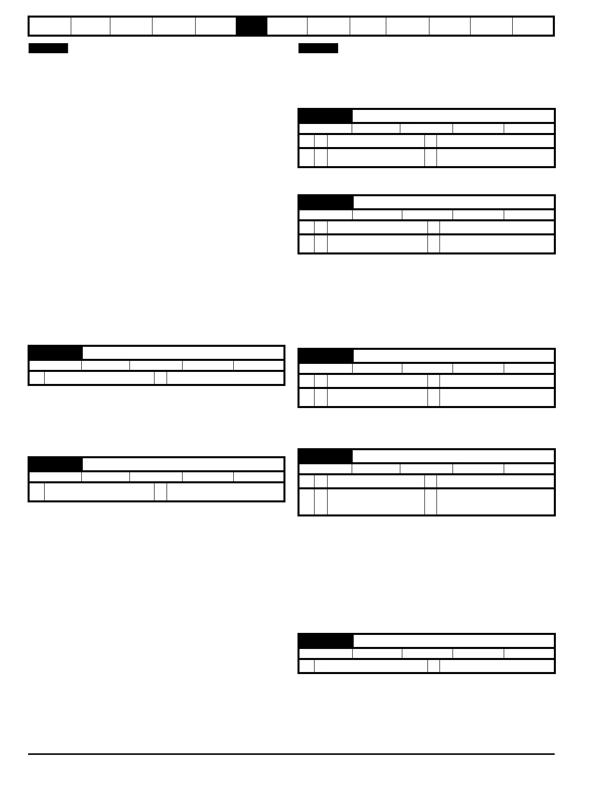
0.40 {5.12} Autotune
RW Bit P
Ú
0 or 1
Ö
0
0.41 {5.18} PWM switching frequency
RW Txt
Ú
3 (0), 4.5 (1), 6 (2), 9 (3),
12 (4) kHz
Ö
3 (0)
NOTE
0.42 {5.11} Motor - number of poles
RW Txt P
OL
Ú
2 to 32 poles
Ö
4 (1)
CL
Ú
VT> 2 to 32 poles
SV> 2 to 32 poles
Ö
4 (1)
6 (2)
0.43 {5.10} Motor - power factor
RW Uni S P
OL
Ú
0 to 1.000
Ö
0.92
CL
Ú
VT> 0 to 1.000
SV> 1
Ö
0.92
1.0
0.44 {5.09} Motor - rated voltage
RW Uni
OL
Ú
0 to 480
Ö
400
CL
Ú
VT> 0 to 480
SV> 0
Ö
460
0
0.45 {5.08} Motor - rated speed
RW Uni
OL
Ú
0 to 6,000rpm
Ö
0
CL
Ú
VT> 0 to 30,000rpm
SV> 0 to 30,000rpm
Ö
EUR> 1,450
USA> 1,770
0
0.46 {5.07} Motor - rated current
RW Uni
Ú
0 to FLC A
Ö
FLC
NOTE