Safety
Information
Product
Information
Mechanical
Installation
Electrical
Installation
Getting
Started
Menu 0
Running
the motor
Optimisation Macros
Advanced
Parameters
Technical
Data
Diagnostics
UL Listing
Information
146 Unidrive User Guide
www.controltechniques.com Issue Number: 9
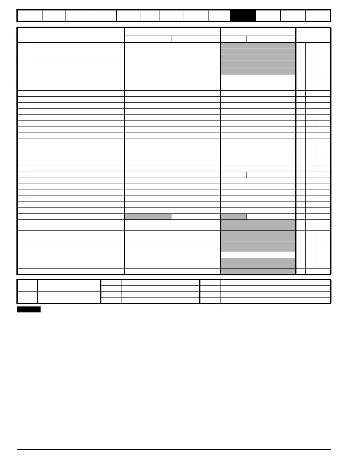
Where a parameter is represented by a text value, the value in brackets
in the range column is the setting used for serial communications.
Parameter
Range(
Ú) Default(Ö)
Type
OL CL OL VT SV
7.01 Analog input 1 ±100.0 %
RO Bi P
7.02 Analog input 2 ±100.0 %
RO Bi P
7.03 Analog input 3 ±100.0 %
RO Bi P
7.04 Heatsink temperature
0 to 100
o
C
RO Uni P
7.05 Control board temperature
0 to 100
o
C
RO Uni P
7.06 Analog input 1 mode
selector {0.24}
VOLt (0), 0 - 20 (1), 20 - 0 (2), 4 - 20.tr (3),
20 - 4.tr (4), 4 - 20.Lo (5), 20 - 4.Lo (6),
4 - 20.Pr (7), 20 - 4.Pr (8)
VOLt (0) RW Txt R
7.07 Analog input 1 offset trim ±10.000 % 0 RW Bi P
7.08 Analog input 1 scaling 0 to 4.000 1.000 RW Uni
7.09 Analog input 1
invert 0 or 1 0 RW Bit
7.10 Analog input 1 destination parameter Pr 0.00 to Pr 20.50 Pr 1.36 RW Uni R P
7.11 Analog input 2 mode
selector {0.25}(as Pr 7.06)VOLt (0)RWTxtR
7.12 Analog input 2 scaling 0 to 4.000 1 RW Uni
7.13 Analog input 2
invert 0 or 1 0 RW Bit
7.14 Analog input 2 destination parameter {0.26}Pr 0.00 to Pr 20.50 Pr 1.37 RW Uni R P
7.15 Analog input 3 mode
selector
VOLt (0), 0 - 20 (1), 20 - 0 (2), 4 - 20.tr (3) ,
20 - 4.tr (4), 4 - 20.Lo (5) , 20 - 4.Lo (6),
4 - 20.Pr (7), 20 - 4.Pr (8), th.SC (9), th (10)
EUR> th (10), USA> VOLt (0) RW Txt R
7.16 Analog input 3 scaling 0 to 4.000 1.000 RW Uni
7.17 Analog input 3
invert 0 or 1 0 RW Bit
7.18 Analog input 3 destination parameter Pr 0.00 to Pr 20.50 Pr 0.00 RW Uni R P
7.19 Analog output 1 source parameter Pr 0.00 to Pr 20.50 Pr 5.01 Pr 3.02 RW Uni R P
7.20 Analog output 1 scaling 0 to 4.000 1 RW Uni
7.21 Analog output 1 mode
selector VOLt (0), 0 - 20 (1), 4 - 20 (2) VOLt (0) RW Txt R P
7.22 Analog output 2 source parameter Pr 0.00 to Pr 20.50 Pr 4.02 RW Uni R P
7.23 Analog output 2 scaling 0 to 4.000 1.000 RW Uni
7.24 Analog output 2 mode
selector VOLt (0), 0 - 20 (1), 4 - 20 (2) VOLt (0) RW Txt R P
7.25 Calibrate analog input 1 full scale 0 or 1 0 RW Bit
7.26 V/f sample time
0 to 5.0 ms 4.0 RW Uni
7.27
Analog input 1 current-loop loss
indicator
0 or 1
RO Bit P
7.28
Analog input 2 current-loop loss
indicator
0 or 1 RO Bit P
7.29
Analog input 3 current-loop loss
indicator
0 or 1 RO Bit P
7.30 Analog output set-up
enable 0 or 1 0 RW Bit
7.31
UD78 large option module fitted
indicator
0 or 1 RO Bit P
7.32 IGBT junction temperature 0 to 150 °C
RO Uni P
RO Read Only parameter
Uni Unipolar variable parameter R Reset required for new value to take effect
Bi Bipolar variable parameter S New parameter-value saved at power-down
RW Read / Write parameter
Txt Text variable parameter P Protected; forbidden as destination parameter
Bit Bit parameter FLC Full-load current (max. continuous), Pr 11.32 {0.33}
NOTE