Safety
Information
Product
Information
Mechanical
Information
Electrical
Information
Getting
Started
Menu 0
Running
the motor
Optimisation Macros
Advanced
Parameters
Technical
Data
Diagnostics
UL Listing
Information
198 Unidrive User Guide
www.controltechniques.com Issue Number: 9
12 Diagnostics
The display on the drive gives various information about the status of the
drive. These fall into three categories:
Trip indications
Alarm indications
Status indications
12.1 Trip indications
If the drive trips, the output is disabled so that the drive stops controlling
the motor. The lower display indicates that a trip has occurred and the
upper display shows the trip.
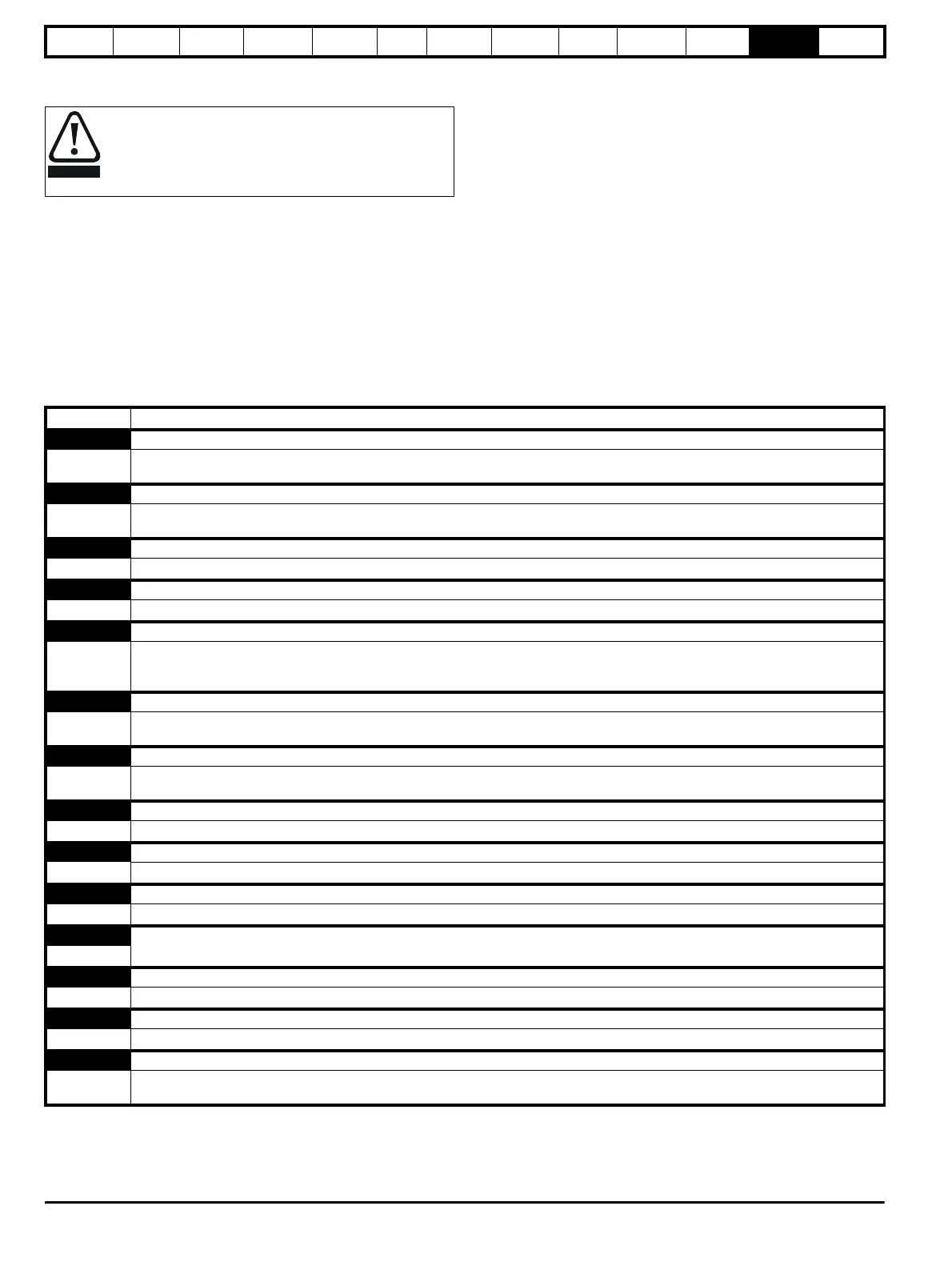
Table 12-1 Trip indications
Users must not attempt to repair a drive if it is faulty, nor
carry out fault diagnosis other than through the use of the
diagnostic features described in this chapter.
If a drive is faulty, it must be returned to an authorized Control
Techniques distributor for repair.
WARNING
Trip Diagnosis
AN1.diS UD78> Servo large option module displaced
37
UD78 Servo large option module was displaced or removed.
Ensure that the module is fitted correctly.
cL1 Current signal loss on analog input 1
27
Loss of signal current on Analog input 1 (terminals 5 and 6), when configured for 4 to 20mA trip on loss current signal input. (Trip
level 3mA.)
cL2 Current signal loss on analog input 2
28 Loss of signal current on Analog input 2 (terminal 7), when configured for 4 to 20mA trip on loss current signal input. (Trip level 3mA.)
cL3 Current signal loss on analog input 3
29 Loss of signal current on Analog input 3 (terminal 8), when configured for 4 to 20mA trip on loss current signal input. (Trip level 3mA.)
ConF n Configuration has changed to n modules
150 to 158
No. of modules has changed to n modules (size 5 only).
Check DIP switches on control module correspond with the slide switch address settings on the power modules.
Save parameters to clear this trip on next power-up.
EEF EEPROM Fault
31
Fault in the internal EEPROM causing loss of parameter values.
This trip can only be reset by loading default parameters and saving parameters.
ENC.OUL Encoder power supply overload
10
Check encoder power supply wiring and encoder current requirement
Maximum current = 300mA @ 15V and 5V
ENC.PH1 Encoder phase 1 trip
11 Encoder U phase commutation signal missing or the motor did not rotate.
ENC.PH2 Encoder phase 2 trip
12 Encoder V phase commutation signal missing.
ENC.PH3 Encoder phase 3 trip
13 Encoder W phase commutation signal missing.
ENC.PH4 Encoder phase 4 trip
14 Encoder U V W commutation signals connected incorrectly.
ENC.PH5 Encoder phase 5 trip
15 Encoder A channel signal missing.
ENC.PH6 Encoder phase 6 trip
16 Encoder B channel signal missing.
ENC.PH7 Encoder phase 7 trip
17
Encoder A and B channel signals connected incorrectly.
Resolver or SINCOS encoder, SIN and COS connections connected incorrectly or the phase sequence of the motor is reversed.