4 Modbus/TCP
4-2 Ethernet Option Board /
700.002 735 AE01
4.1 MODBUS/TCP vs. MODBUS RTU
Compared to the MODBUS RTU protocol, the MODBUS/TCP differs mostly in error checking and slave
addresses. As the TCP already includes an efficient error checking function, the MODBUS/TCP protocol does
not include a separate CRC field. In addition to the error checking functionality, the TCP is responsible for
resending packets and for splitting long messages so that they fit the TCP frames.
The slave address field of the MODBUS/RTU is named as the unit identifier field in MODBUS/TCP, and it is
only used when one IP address stands for several endpoints.
4.2 Ethernet Option Board's Modbus Addresses
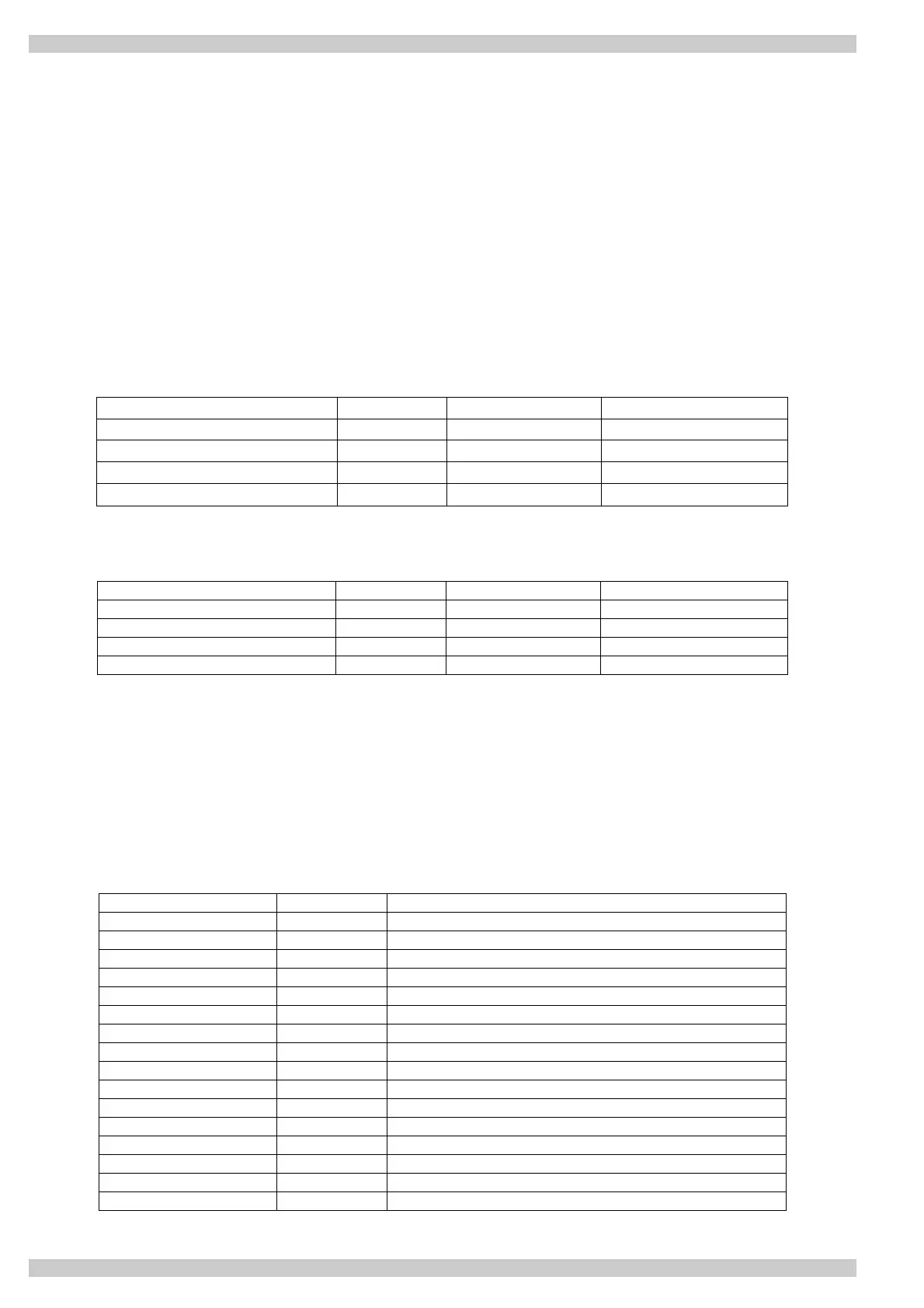
A Modbus/TCP class 1 functionality has been implemented in OPT-CI board. The following table lists
supported MODBUS registers.
Name Size Modbus address Type
Input Registers 16bit 30001-3FFFF Read
Holding Register 16bit 40001-4FFFF Read / Write
Coils 1bit 00001-0FFFF Read / Write
Input discretes 1bit 10001-1FFFF Read
Table 4-1: Supported Registers
Name Size Modbus address Type
Input Registers 16bit 30001-3FFFF Read
Holding Register 16bit 40001-4FFFF Read / Write
Coils 1bit 00001-0FFFF Read / Write
Input discretes 1bit 10001-1FFFF Read
Table 4-2: Supported Registers
4.3 Coil (0x01) Register
The Coil register represents data in a binary form. Thus, each coil can only be in mode “1” or mode ”0”. Coil
registers can be written using the MODBUS function 'Write coil' (5) or the MODBUS function 'Force multiple
coils' (16). The following tables include examples of both functions.
4.3.1 0001 –00016 Control Word (Read / Write)
Address Function Purpose
0001 RUN/STOP Control word, bit 1
0002 DIRECTION Control word, bit 2
0003 Fault reset Control word, bit 3
0004 FBDIN1 Control word, bit 4
0005 FBDIN2 Control word, bit 5
0006 FBDIN3 Control word, bit 6
0007 FBDIN4 Control word, bit 7
0008 FBDIN5 Control word, bit 8
0009 BusCtrl Control word, bit 9
0010 BusRef Control word, bit 10
0011 FBDIN6 Control word, bit 11
0012 FBDIN7 Control word, bit 12
0013 FBDIN8 Control word, bit 13
0014 FBDIN9 Control word, bit 14
0015 FBDIN10 Control word, bit 15
0016 FBFaultIN Control word, bit 16
Table 4-3: Control Word Structure