Service Handbook OGS/OGB
Step 2: Check gas panel and possible replacement according
to the desired gas type.
i
Information:
The gas panel (see following picture) functions as a gas nozzle for the blower
burner.
The gas panel is assembled between the gas valve and the Verturi.
For the size of the gas panel to be assembled, refer to Chart 2.
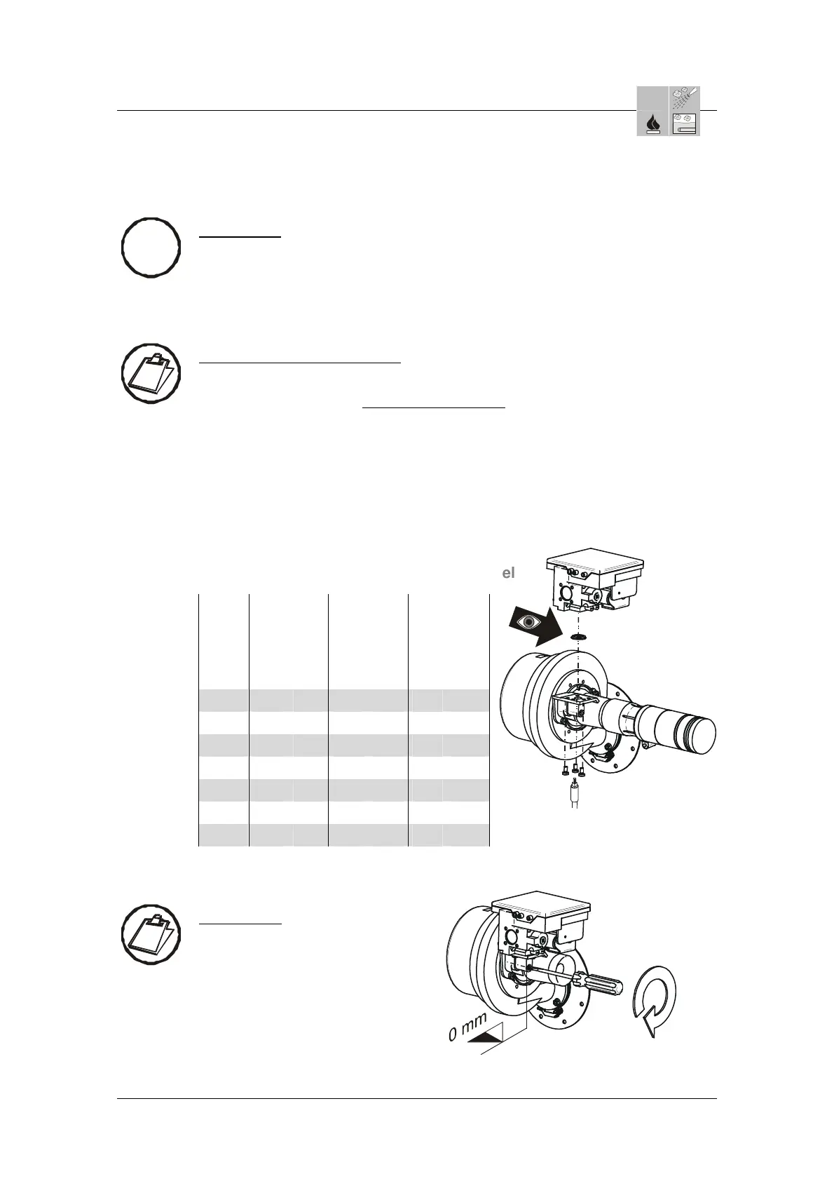
Instructions: Check gas panel
Shut off the gas supply.
Remove the 3 screws underneath the Venturi
on the gas valve.
Remove the gas valve/ firing automat.
Check the gas panel (Number code = Ø is engraved on the gas panel) and
replace if necessary.
Reassemble the gas valve/firing automat with the panel and seal and screw it
tightly onto the Venturi.
Re-open the gas supply and check the entire unit for gas tightness with a
leakage spray or gas detector.
Page 4 / 12
Chart 2: Number code = Ø of the gas panel
OGB+
OGS
Erd/
Natural
Gas
H G20
Erd/
Natural
Gas
LL G25
Flüssig/
LP Gas
B/P
G30/G31
HL DE HL DE HL DE
6.10
620 620 660 660
470 470
6.20
565 565 630 630 430 430
10.10
565 565 630 630 430 430
10.20
620 620 680 680 470 470
12.20
620 620 680 680 470 470
20.10
565 620 630 680 430 470
20.20
620 620 680 680 470 470
Step 3: Check screws on Venturi
Instructions:
Check whether the screws
on the Venturi are flush with
the connection piece.
AS/11-2011 / Part No.: 7016396 6_25e_Readjusting the Gas valves_d
 Loading...