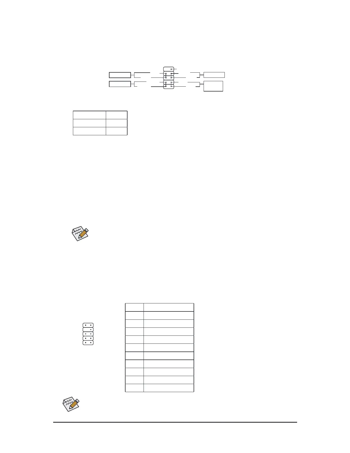
9) F_PANEL (Front Panel Header)
Connect the power switch, reset switch, and system status indicator on the chassis to this header according
to the pin assignments below. Note the positive and negative pins beore connecting the cables.
System Status LED
S0 On
S3/S4/S5 Off
• PW (Power Switch):
Connects to the power switch on the chassis ront panel. You may congure the way to turn o your
system using the power switch (reer to Chapter 2, "BIOS Setup," "Settings\Platorm Power," or more
inormation).
• HD (Hard Drive Activity LED):
Connects to the hard drive activity LED on the chassis ront panel. The LED is on when the hard drive
is reading or writing data.
• RES (Reset Switch):
Connects to the reset switch on the chassis ront panel. Press the reset switch to restart the computer
i the computer reezes and ails to perorm a normal restart.
• NC: No connection.
• PLED (Power LED):
Connects to the power status indicator on the chassis ront panel. The LED
is on when the system is operating. The LED is o when the system is in S3/
S4 sleep state or powered o (S5).
12
910
NC
PLED-
PW-
PLED+
PW+
HD-
RES+
HD+
RES-
Power Switch
Hard Drive
Activity LED
Reset Switch
Power LED
The ront panel design may dier by chassis. A ront panel module mainly consists o power
switch, reset switch, power LED, hard drive activity LED and etc. When connecting your chassis
ront panel module to this header, make sure the wire assignments and the pin assignments
are matched correctly.
9
1
10
2
10) F_AUDIO (Front Panel Audio Header)
The ront panel audio header supports High Denition audio (HD). You may connect your chassis ront
panel audio module to this header. Make sure the wire assignments o the module connector match the
pin assignments o the motherboard header. Incorrect connection between the module connector and the
motherboard header will make the device unable to work or even damage it.
Some chassis provide a ront panel audio module that has separated connectors on each wire
instead o a single plug. For inormation about connecting the ront panel audio module that has
dierent wire assignments, please contact the chassis manuacturer.
- 16 -
Pin No. Denition
1 MIC L
2 GND
3 MIC R
4 NC
5 Head Phone R
6 MIC Detection
7 SENSE_SEND
8 No Pin
9 Head Phone L
10 Head Phone Detection