VR-32 Regulator and CL-2A Control
2-3
SETTING THE CL-2A CONTROL FOR SERVICE
This section describes the user selectable control settings and
aides in determining the correct values for the application.
There are a total of seven control settings to be determined:
1. Voltage setting, continuously variable from 105 to 135
volts.
2. Bandwidth setting, variable from 1 volt to 6 volts in 0.5
volt increments.
3. Time delay setting, variable from 10 seconds to 120 sec-
onds in 10 second increments, or by using the time dou-
bling feature, from 20 seconds to 240 seconds in 20 sec-
ond increments.
4. Line drop compensation for resistance, continuously vari-
able from 0 to 24 volts.
5. Line drop compensation for reactance, continuously vari-
able from 0 to 24 volts in 1 volt increments.
6. Line drop compensation control switch for establishing the
polarity (±) for each of the R & X line drop compensation
elements.
7. Control operating mode, selectable between sequential
mode, time integrating, or voltage averaging. This feature
is implemented via a dip switch, located on the printed cir-
cuit board.
Voltage Setting
All Cooper Power Systems VR-32 regulators have provisions
for operation at system voltages lower than the nameplate rat-
ing. The correct voltage setting for the application is dependent
upon the regulator rating and the system voltage on which it is
installed. The regulator nameplate always indicates the voltage
setting for the given application that produces an output regu-
lated to the 120 volt base voltage. (This is explained in detail in
the Control operation section of the manual, page 2-4.) The
user simply sets the voltage setting for the value indicated on
the nameplate, unless it is desired to operate at a higher or
lower voltage level than nominal.
Bandwidth
The bandwidth is defined as the total voltage range around the
voltage setting which the control will consider as a satisfied condi-
tion. As an example, a 2V bandwidth on a 120 volt setting means
the operational timer will not activate until the voltage is below
119V or above 121 V. When the voltage is in-band, the band edge
lights are off and the timer (time delay) is off, so no relay closure
can occur. Selection of a small bandwidth will cause more tap
changes to occur, but will provide a more “tightly” regulated line.
Conversely, a larger bandwidth results in fewer tap changes, but
at the expense of better regulation. Selection of the bandwidth
and time delay settings should be made recognizing the interde-
pendence of these two parameters.
Time Delay
The time delay is the period of time (in seconds) that the control
waits from when the voltage first goes out-of-band to when the
relay closure occurs. If a rapid response is required, a smaller
setting should be used. If several devices on the same line are to
be coordinated, longer time delay settings may be required to
allow the proper devices to operate in the desired sequence.
On the front panel of the CL-2A regulator control, the time
delay values are prominently marked through 120 seconds. A fea-
ture of this control, called time doubling, permits time delay
sequences up to 240 seconds to occur. This feature simply dou-
bles the actual setting shown by the switch on the panel. It is
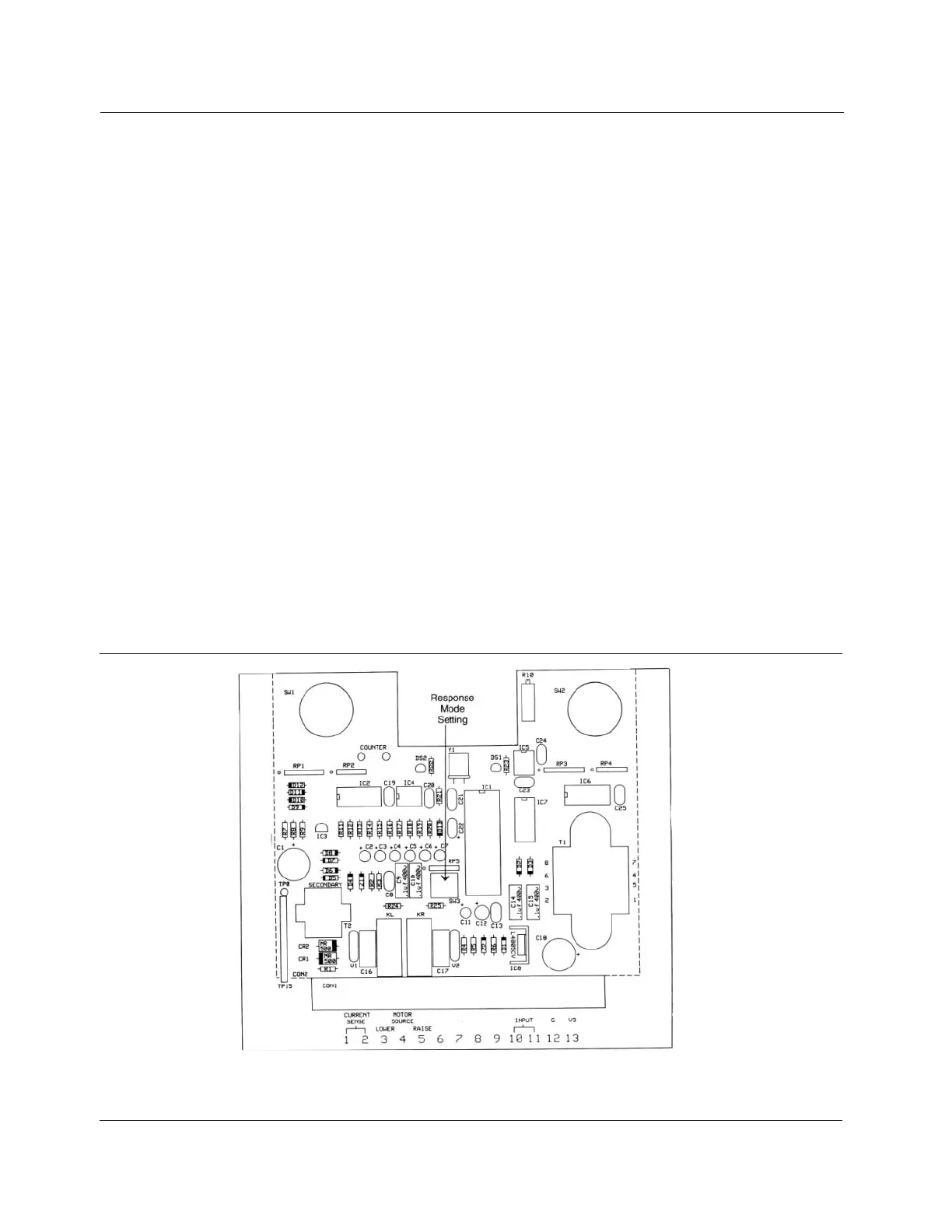
implemented by setting position 4 on the dip switch, located on
the printed circuit board (Figure 2-2).
Figure 2-2.
Printed Circuit board.