5-1
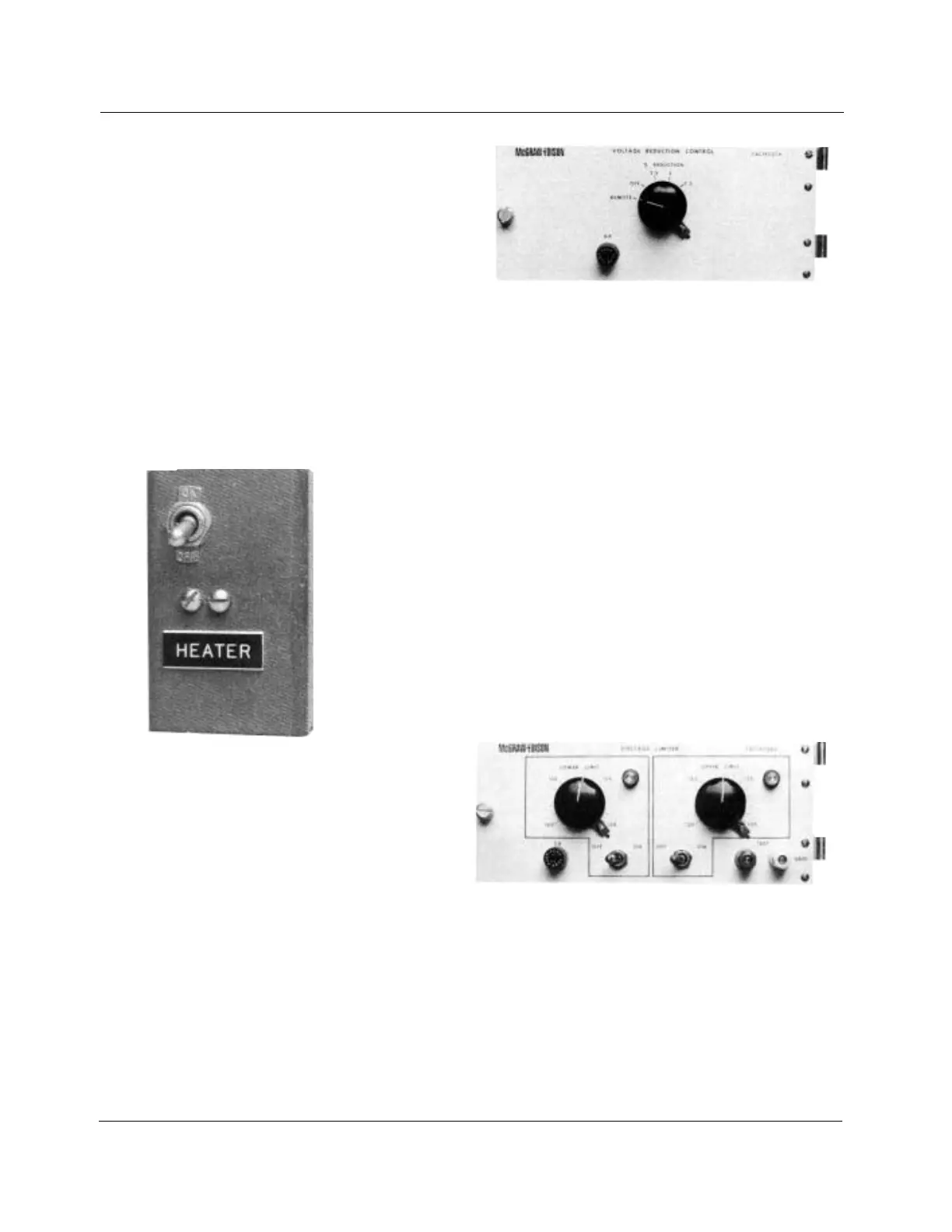
Figure 5-1.
Heater.
Figure 5-2.
Voltage reduction control.
Figure 5-3.
Voltage limiter.
ACCESSORIES - Section 5
The following accessories are available for use with the regu-
lator control to perform various functions. They can be mount-
ed in the same enclosure as the control; however, if a number
of them are used, a second enclosure is required. Most can
be either installed at the factory or retrofit in the field by the
customer. Those that can be retrofit are listed in the spare
parts section.
Heater Assembly
The thermostatically controlled heater assembly is best used
in high-humidity areas. The heater assembly shown in Figure
5-1 is located in the lower-left corner of the rear panel.
The heater can be manually turned on or off by means of
the toggle switch located on the heater assembly. In the ON
position the thermostat in the heater assembly will turn the
heater on when the temperature falls below 85˚F. The thermo-
stat turns the heater off when the temperature exceeds 100˚F.
For full details refer to
S225- 10-1 Supplement 2.
S225-10-5
Voltage Reduction Control
The voltage reduction control accessory (Figure 5-2) can pro-
vide system load management through its ability to trigger the
regulator to reduce voltage. Its application is ideal in situations
where power demands surpass available capacity and where
there are extraordinary peak loads.
The voltage reduction control provides three reduction lev-
els: 2-1/2%, 5%, and 7-1/2% of regulated voltage level. Any
one of these three levels can be manually selected by turning
the single control on the panel to the desired percent reduc-
tion. The reduction steps are provided by an autotransformer.
Through the use of plug-in relays and appropriate percent-
age connections to the rear terminal strip, any of these three
reduction levels can be selected via remote activation signal.
Many standard relay coil voltage selections - ac or dc - are
available to match the relay to the remote control system. For
full details refer to
S225-10-1 Supplement 3.
Voltage Limiter
The voltage limiter accessory (Figure 5-3) permits a regulator’s
maximum and minimum output to be selected, protecting the
consumer from abnormally high or low voltages resulting from:
1. Defective functioning of the regulator control panel.
2. Abnormal loading of the feeder.
3. Inaccurate regulator control settings (voltage level, bandwidth,
line drop compensations, etc).
4. Heavy loading by the first customer while there is a leading
power factor on the feeder.
5. Light loading at the first customer with heavy loading on the
feeder at the same time.
The lower-limit control can be disabled without influencing the
upper-limit control. Turning the upper-limit control off, however,
disables both controls. With both controls turned off, power may
be applied to the voltage limiter’s external test terminals for oper-
ational checks. The range of the lower-limit setting is 105 to 120
volts; the range of the upper-limit setting is 120 to 135 volts.
The raise or lower motor circuit of the regulator is interrupted
when a set voltage limit is exceeded. This interruption provides
total override of the main control. For full details refer to S225-
10-1 Supplement
4.